Sunday, January 29, 2006

Motor Project # 8 - Vital Fluids

From Steve Hannes - Jaguar X-Type Fluids/Capacities

NOTE: This covers the X-Type, however, I've included two links that give fluid information for all models.

SPECIAL WARNING: The fluids used in the Jaguar X-Type are a new generation "extended life", "long life" or "sealed for life" fluids. Be VERY careful replacing any of these fluids with traditional natural petroleum or synthetic products. Some suppliers that want to sell lubricants are going to give you a recommendation if you ask for their "compatible" lubricant, but the question is bigger than that. Look at the Ford or Jaguar specification that I've listed for each component. You must ensure the replacement lubricant is compatible with the spec. For example: The new generation M2C192A Ford spec. for the differential lubricant is a much different product than just a standard 75W140 synthetic gear oil. I've put dozens of hours in researching brands, calling suppliers and assembling the information below. Save yourself some time/effort and take advantage of this work.

RE: Lubricants, Fluids, Sealers and Adhesives Description Specification. I’ve completed an exhaustive research matching Jaguar (Ford) specifications with commercial brand oils and lubricants. And I now know more than I ever wanted about fluids specifications! Ford (and Jaguar), like all manufacturers, creates an engineering specification for fluids, then usually manufactures their own or partners with a supplier. Jaguar has partnered with Castrol since 07/2004. Commercial lubricant suppliers then choose whether to offer products that meet manufacturer’s specifications. Unfortunately, not all popular brands choose to specify compliance with all manufacturers. That doesn’t mean they do not, but they don’t market products for specification compliance.

A good example of this is two manufacturers popular with the race circuit – Royal Purple and Redline. Redline makes synthetic gear lubricants for transmissions, transfer cases and differentials. They do not advertise manufacturer’s specification compliance in their product spec sheets, and they did not answer my written request for that information. Therefore, I don’t list their products and you’re on your own if you want to substitute their products for Jag/Ford specs. Royal Purple makes synthetic oils and lubricants as well as traditional oils. They too do not advertise, nor would they answer written requests for spec compliance. They actually recommend synthetic motor oil (10W 40) for manual transaxles and in compliance with WSD-M2C200-C, but call me skeptical. Again, you won’t find these products on my list. For all of my research I use the factory vehicle specifications by Jaguar. I've attached a Jaguar bulletin regarding fluids to the bottom of this post. Note the warnings about unauthorized fluids and impact on warranty. "Fluids are subject to audit on warranty claims." BTW – If anyone wants their own copy of the vehicle specifications by Jaguar, someone published the 2003 PDF version on the web. Find it at: http://jaguar.telko.ru/Vehicle%20Specification%20(1998-2003%20all%20models).pdf General Specifications from JTIS, details follow: Engine oil (EUROPE), SAE 5W-30W SS-M2C-913A – N/A in this doc. Engine oil (US), SAE 5W-30 ILSAC GF3, API SJ – See Below Engine assembly lubricant SQM-2C9003 AA EP90 – Used to assemble engine components like camshafts, bearings, etc. Any internal engine part that might have metal to metal contact on startup before engine oil can get to it. These are all greases that dissolve and go into solution with motor oil. Brands: Redline Assembly Lube; Torco MPZ Assembly Lube pn. MPZ-AL; Belray Assembly Lube Sta-Lube Assembly grease – NOTE: None of these could be verified as complying with SQM-2C9003 AA EP90, however, all are meant to be compatible with motor oil. Hose assembly surfactant ESE-M99B144-B Brands: Merpol (is a trade name). Metal surface cleanerWSW-M5B392-A Could not find a supplier SealantWSS-M4G323-A6 Could not find a supplier Spark plug grease'Neverseeze' ESE M12 A4A Brands: Permatex Anti-Seize Compound Engine Oil: JTIS Spec (US): Engine oil (US), SAE 5W-30 ILSAC GF3, API SJ 5W30 ONLY – As the hydraulically operated VVT is extremely sensitive to viscosity changes. 5W30 gives the best viscosity range results with VVT. Never use a higher W number than 5W in the Duratec with VVT. Wider viscosity ranges or weights over 30 can defeat the hydraulic oil pump under certain temperature conditions and cause it not to respond, even though the ECM sends the electronic signal to shift. Jag service intervals change oil and filter every 10K – My interval is every 5K. Brands: Castrol GTX 5W30 (Castrol is actually recommended by name and logo in the Jaguar factory specifications dated 07/2004); most other shelf oil brands. Some believe in synthetics. JTIS doesn’t really say yes or no. Probably OK to use, but don’t take that as my recommendation. Capacity: 2.5L and 3.0L. 7 US Qts. Rear Differential Oil: JTIS Spec: M2C192A synthetic, SAE 75W140 synthetic gear lubricant. The M2C192A Ford spec. is a synthetic gear oil with a friction modifier already added. You do NOT want to use a standard synthetic gear oil w/o a modifier or that does not meet M2C192A. It’s important that you don’t over or under do the modifier if you’re going to add your own. Jag calls this unit sealed for life and changes are not necessary. Not for me – every 30K to 60K miles. Brands: Sta-Lube Syn GO 75W 140 Synthetic states M2C192A compliance on the label; Capacity: 2.5L and 3.0L. 1.268 US Qts. (2.5 Pts.) Transfer Case Oil: JTIS Spec: M2C192A synthetic, SAE 75W140 synthetic gear lubricant. Jag spec, again, sealed for life. I will change every 30K to 60K along with the diff. same fluid spec in both. I’m using the Sta-Lube Syn Go ($38 for a two quart container). The two quart is enough for both diff and Xfer case. Brands: Sta-Lube Syn GO 75W 140 Synthetic Capacity: REFILL – 2.5L and 3.0L. 1.16 Pts. (18.6 Ozs.) Manual Transaxle Oil: JTIS Spec: WSD-M2C200-C Synthetic, SAE 75W90 Synthetic Gear Lubricant. This is the infamous “lifetime” lubricant specification. It is very new on the scene. Manufacturers are not hitting the commercial market with this product (or the automatic trans fluid) because the units don’t require changing. This has been particularly frustrating in research and I’ve spent the most time on both transaxles. For the manual, and coincidentally, Motorcraft has a WSD-M2C200-C compliant fluid, I suspect, could be purchased at any Ford dealer. I have yet to try, but will be my choice. Amsoil also refers to this spec as compliant. Castrol BOT 130M is compliant, but I cannot find it for sale in the states. Brands: Motorcraft XT-M5-QS (Is the best if you can find it); Amsoil AGR or TGR; Castrol BOT 130M Capacity: 2.5L and 3.0L.1.84 US Qts. (3.7 Pts.) Auto Transaxle Oil: JTIS Spec: WSS-M2C922-A1 automatic transmission fluid. From the Jaguar spec 7/2004 - Use of any other fluids may result in a transmission malfunction or failure. Intervals Normal Maintenance Not necessary. Filled for life. Severe Duty Maintenance Change the fluid at 48,000 km (30,000 miles) intervals. It was very difficult interpreting the factory spec. Then I discovered a factory bulletin online. It is attached at the bottom of this post and an excerpt is listed for brands. Shell is a popular brand in the US and it looks to be a Mercon V type fluid. Use the Shell pns. listed to match compatibility. Jatco makes their own recommended fluid, but I have no idea how one would purchase it. Brands: All of the following come from the service bulletin attached on the bottom of this post - Recommended fluids Esso LT 71141; Shell ATF 3403 M115; Shell M1375.4; MERCON V XT-5-QM ATF; IDEMITSU K17; Jatco 3100 PL085. Jatco is preferred if you can find it. Capacity: 2.5L and 3.0L. Approx 8.32 US Qts. Refill – (Initial fill 9.3 qts) Engine Coolant: JTIS Spec: WSS M97B44 D. This is compatible with long life marketed anti-freeze. Originally developed for GM, called Dex-cool, this fluid is pink/orange in colouor, not green. Long life specifies 5 year 150,000 mi changes. I don’t agree and change mine every 12 to 24 months max. Brands: Prestone Extended life 5/150. This is a new generation (pink/orange) coolant compatible with all coolants - green, pink, orange, or whatever. Capacity: 10.6 qts 3.0L and 2.5L – but expect that you might not get the entire system drained from the heater core and engine block. Brake Fluid: JTIS Spec: Super Dot 4 – From research, several manufacturers offer super dot 4, but hard to find in local parts stores. It can be ordered online from most suppliers. The motorcycle world seems to use it more commonly, so look for it at a local cycle shop. BTW - Synthetic brake fluids are becoming very popular and, just like motor oils, Jaguar doesn't say one way or another whether to use or avoid Synthetic brake fluid. The factory specifies purging the entire system every two years (VERY important as brake fluids, even synthetics are hydroscopic). My interval is once a year. Brands: Castrol Super dot 4; Belray Super dot 4; Penszoil super dot 4 – many others. Capacity: estimated less than 1 qt. with reservoir and manual clutch. The auto will use less. Power Steering Fluid: JTIS Spec: Mobil ATF meeting Dexron 3 Specification. I don’t purge or change power steering fluid, just watch for leaks or steering resistance. Sometimes a fluid change helps, but not always. Brands: Any good quality Dexron 3 commercial product. Capacity: 1.2 Qts. Approximately. RESEARCH Sources (online): Find a factory tech bulletin at: http://www.wwwboards.auto.ru/jaguar/5301.html Technical Service Bulletin No.JagA100-000413 December 2004 Subject/Concern : Jaguar - Recommended Castrol Lubricants and Fluids in Service Models : XJ Range 1998- Vin range : 812317 Onwards XK Range 1998- Vin range : 001246 Onwards S-TYPE 1999- Vin range : L00600 Onwards X-TYPE 2001- Vin range : C00344 Onwards

Saturday, January 28, 2006

Motor Project # 7 - Timing is Everything

From Steve Hannes - This project is meant to inform and educate. UPDATE - Feb 04-2006 - I am correcting an error in an earlier publishing of this post. I incorrectly concluded the valve shims and buckets were one piece. Since then I discovered they, in fact, are two pieces. Tolerances are very close. In mechanical engineering terms the fit of shim to bucket recess is called a "working fit", less than .0005" tolerance. I needed to heat the bucket assembly to 200 deg F to assist in removal. Part of the problem was the oil film underneath the shim. With cold oil the shim barely moves (rotates) in the bucket. Only when it was heated did the tolerances and oil viscosity change enough to remove the shim. Also, there are no recesses or notches to assist in removal like in other designs. Here is an additional picture of the two shims and buckets. Now I'll purchase smaller shims to bring these two intake valves to the correct tolerance. From the last project, you'll recall that I took valve clearance measurements on a 3.0L Jaguar Duratec with 15K miles on it. All intake and exhaust vales were to spec except for two intake valves on the right bank: one out of the pair for the #1 cylinder, and one of the pair for the #2. These two valves measured .004" clearance and spec is .007" to .009". These are almost half the minimum spec and MUST be corrected. Remember that I use a cylinder numbering and firing order that matches generic Duratecs so this won't match what you see in the JTIS CD (which is wrong, wrong, wrong).

In this post I'll pursue those two valves and correct the clearances. I'll just cover what I need to get to those two shims. I'll put assembly in some future post; otherwise, this would take up a lot of space and pics. The Jaguar Duratec head design is unique in its application for the X-Type. The 2.5L and 3.0L both use the same layout, except the valves are slightly larger in the 3.0L. This is a double overhead cam design with a mechanical valve train and not hydraulic as other Duratecs are. Jaguar designed a variable valve timing (VVT) feature and works by varying the cam positions of the intake cams only. Their positions change in relation to the position of the crankshaft and exhaust cams to optimize torque during the rpm range from idle to redline. The system works using a hydraulic two-port pump design, fed with engine oil and pressure, and controlled by the ECM. The ECM sends a signal to the pumps to close one port, open the other to advance the intake cams to create the optimal combination of performance/fuel economy/emissions at certain places during the RPM/load range, then sends the opposite signal (close that port, open the first) to retard the intake cams. These electric/hydraulic pumps (one for each intake cam) are VERY sensitive to oil viscosity, so it is important to use the "right" oil weight, otherwise, the VVT might not function even though the ECM sends signals to advance or retard. 5W 30 multi-grade is the best weight range for most driving conditions and tested to be the required weight by Jaguar. Note that the engine oil cap has 5W 30 printed on its top. If another weight oil is used in a Duratec the W should never be higher than 5W, so the only other option might be 0W 30. 
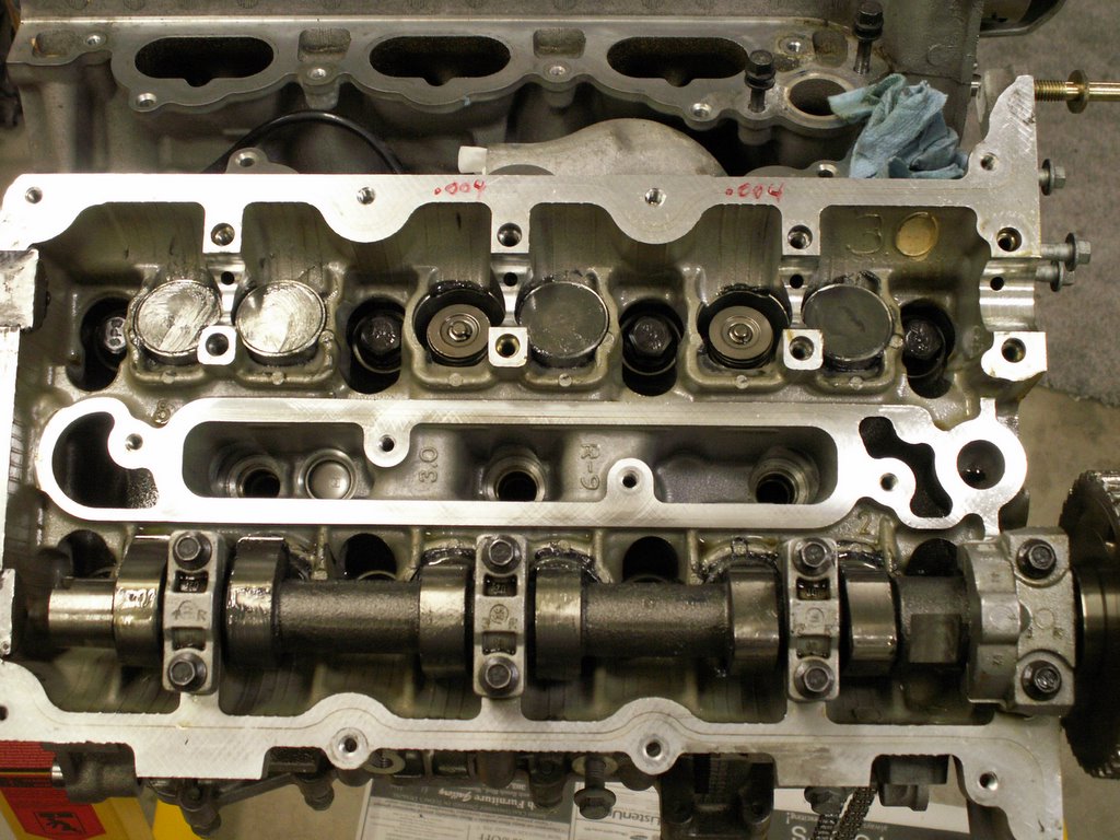
Enough philosophy - let's get our hands dirty. If you remember from past posts, I have the Duratec torn down to expose the cams. It is down to the block and heads, but the timing cover was left in place. Here we'll remove the timing cover and timing chains so the intake cam can be removed, then we can finally reveal/remove the shim buckets. These shims on buckets control the valve clearance. They are a two piece design (bucket and shim). There is no way around using any special tool to depress the bucket and remove just the shim like so many other mechanical lifter DOHC designs, including other Jaguar engines. If someone has I'd like to hear from them. So, first step is to remove the crankshaft pulley. There is a special Jaguar tool used to hold the pulley from turning anti-clockwise as the retaining bolt is broken loose. Remember, it is critical that the crankshaft only turn clockwise for two reasons - the timing chain tensioners can be damaged if they travel backwards and the journal bearings are specially ground to minimize wear in one direction. If the engine were to turn anti-clockwise, burrs might be created on the bearings - a true no, no. I made my own special tool to hold the crank pulley using an old serpentine belt. Break the retaining bolt loose, then use a three legged gear puller to back the pulley off the crankshaft and key. After the pulley is removed, loosen and remove all of the bolts holding the timing cover in place. With all bolts out, the timing cover needs to be LIGHTLY tapped to break the gasket bonds. It's important to use something soft (such as a piece of wood) with a rubber mallet. Do not hit the cover with a hammer! Place the wood on a non-gasketed surface, then lightly tap the wood - Capish? 
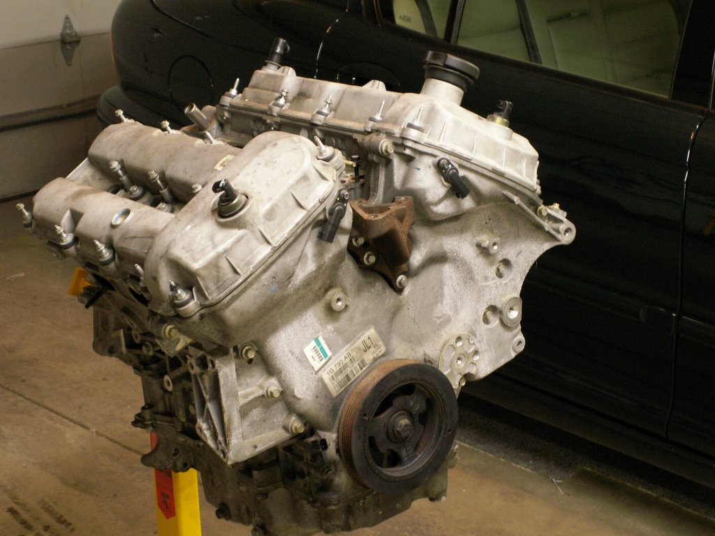
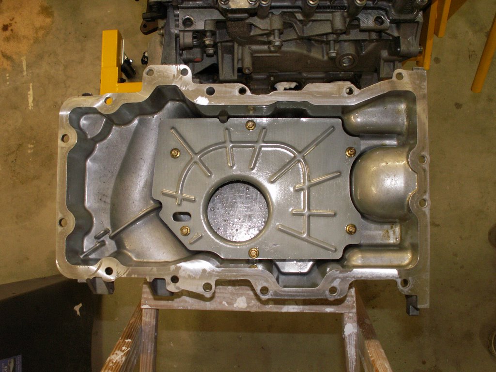
Here is a picture of the timing cover. It is a HUGE (and ugly), heavy aluminum casting. It will come with a crankshaft oil seal (that I will replace before reassembly), the cam position sensors, and the crankshaft position sensor. Integral to the casting are the entire mounting ears (brackets) for the alternator and the power steering pump. Be careful how you handle this piece with its bulk. Some points of interest - there are three formed gaskets used to seal the timing cover. Keep in mind that oil is flowing behind this cover during engine operation. I've put the gaskets in place and they can be seen in this picture. Along with these gaskets, a silicone gasket material must be used in 6 places (2 places each gasket) as these three formed rubber gaskets cross no less than six part lines on the engine assembly - four places at the head/block lines and 2 places at the bedplate lines. I'll include two pictures at the end of this post with closeups of part lines. The fourth seal is the crankshaft seal. It can be seen in place. Part of the oil pan gasket (two oil pan bolts shown in place) and the valve cover gaskets are sealed to the timing cover after its assembly.

On the lower righthand corner of the picture, I've included the crankshaft position gear. It sits freely on the crankshaft behind the timing cover and is held in place by the crankshaft pulley. Take a close look at this gear. It has two keyway notches and, yes, it CAN be installed incorrectly. Make sure the keyway notch that is used on the keyway is the one with the missing tooth - Capish?. You can see the black CP Sensor coming through the timing cover. It's a magnetic pickup and reads the teeth from the CP gear. The missing tooth tells the ECM the engine is at TDC. OK, let's see what we've revealed by removing the timing cover. The cam timing chains are now visible and can be removed. For this project, I will only remove the timing chain for the right bank (left side bank in the picture) where my two "troubled" valves are located. Luckily, the RH bank is the outer timing chain so I can leave the LH bank in place for this project. In this picture you can view the two intake cam electro-hydraulic pumps with the ECM sensor connectors in place. The tops of these can be seen as coming through the valve covers on an assembled running engine. The double timing chain design is a very simple, easy to time layout. Let's focus at only one side at a time. Going clockwise (always clockwise on this engine) a chain runs from the crankshaft over a curved chain track. This is the tensioner side and you can see the spring loaded tensioner block behind the curved tensioner frame. It is a ratcheted design. The spring loaded plunger puts pressure on the curved frame, then a secondary fixed ratchet plunger keeps the tensioner frame from moving backwards. Timing (assembly) is simple and removing (disassembly) is even easier. Three marks need to be observed for each bank, one on the crankshaft (the crankshaft key), then a timing dot on the cams, one on the exhaust and one on the intake. These cam marks are made in manufacturing, however, even if they didn't exist, one can easily get this engine timed, like this: JTIS instructions say: For the RH bank chain removal (first chain), put the crankshaft keyway in the 7 o'clock position. This will put the Exhaust cam marker dot in the 8 o'clock position and the Intake cam timing dot in the 1 o'clock position. If you did this and the cam timing dots were not in these places - why not? Because the gear ratio - cams to crankshaft is 2:1. So if the marks are not where they're supposed to be, rotate the crankshaft 360 degree to the 7 o'clock position again. Now the three marks should be in place. BTW, these JTIS instructions position both intake and exhaust cams at the ideal place where little or no cam lift is exerting pressure on any of the RH bank valves. This ideal position makes cam removal easy and puts the least pressure on the cam journal bearings. But, technically you could remove the timing chain in any position by creating your own timing marks. For the RH bank, from the crankshaft keyway, count 23 teeth on the timing chain in a clockwise direction and make a mark on the RH exhaust sprocket at the 23rd tooth. From that tooth and continuing clockwise count 15 teeth to the intake cam and put a mark at the 15th tooth in the intake cam. Knowing these tooth counts can get you timed again. The LH bank works the same way with the same count, except you are counting from the keyway clockwise 23 teeth to the INTAKE cam first, then 15 to the EXHAUST cam second. The important instruction is always go CLOCKWISE ... Phew! OK - once you have the crankshaft and cams on the RH bank in these ideal clock positions, the next step is to remove the RH timing chain tensioner. Remove the two bolts holding the tensioner in place. This will relieve the tension on the RH bank chain. Now remove the curved tensioner frame. It just sits on a pivotal dowel pin and comes right off. The chain can now be removed, then three bolts to remove the fixed chain track on the back side of the timing train. This fixed chain track is one piece with the hydraulic VVT pump, so it all comes off with three bolts. CAUTION: There is a small o-ring located at the oil feed for the pump between the assembly and the RH head. The recess to hold it is made in the tensioner assembly, not the head. This o-ring is smaller than a dime so it's hard to see. It must be renewed/replaced when reassembling. Here is a picture of what it all lookes like with the RH bank chain and tensioners removed and the chain dropped. I've left the chain on the crank sprocket . Remember, you want the chain to be reassembled in the same direction as it was removed. Do not turn the chain around so it rotates backward from its original assembly. I took only one picture after I removed the RH intake cam, but so far the instructions cover only the chain removal. Now back to the top of the engine. We need to remove the intake cam to expose the the two shims/buckets on the #1 and #2 cylinders. At this point of disassembly the cams are no longer timed to each other or the crankshaft. Remember, if you followed the JTIS steps, the cams are ideally placed so little load exists from valve springs and no piston is at TDC ... a safe place. Loosen EVENLY the cam bearing tower bolts. These bearing caps are on dowel pins so they're not going to readily come up/off with bolt removal. One of these caps is much larger than the other 3 because it not only controls cam rotation runout, but also controls camshaft lateral movement. All of these caps must be marked and must go back in the same place and same orientation. So, whatever your system is, ensure reassembly is the same as what you disassembled.

Here is a picture of the intake cam removed. I've also removed the shims and buckets from the two "problem" intakes. These come out very easily using a shop magnet. The shim and bucket is a two piece design with very close tolerances. In mechanicla engineering this fit is called a "wroking fit" with less than .0005" clearance. I needed to heat the assembly up to 200 deg F so that the oil film underneath the shim would become viscous enough to loosen the shim. Then I needed a special pair of sof pliers and magnet to assist. I tried an air blast, but that did nothing. I'll mic (micrometer) these two shims, then purchase the next smaller shim bucket size from Jaguar. In the picture, you'll notice a lot of grease. This is engine assembly grease. I've coated every moving part of the engine as a "preliminary" lube. Assembly grease greatly assists in bearing lubrication on eventual startup. It is designed to dissolve in engine oil.

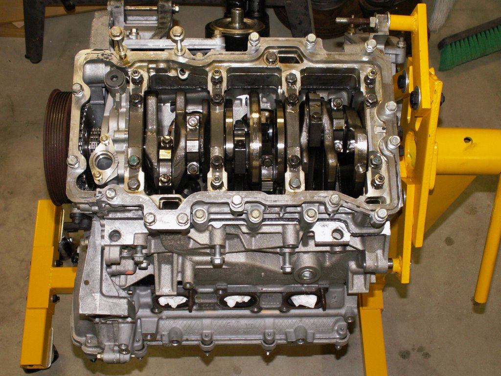
Finally, here is a group picture that shows all of the parts removed to get to the buckets. From the left: the RH chain tensioner; the curved chain track; the two intake bucket shims; the fixed chain guide with the VVT pump; the intake cam from the RH bank. The chain was left on the crank sprocket as it can so easily be reversed.

Here are two closeup pictures of part lines that the timing cover gaskets must cross. The factory uses a small dot of silicone gasket material at these pointe to ensure seal. The factory gasket is not enough to prevent an oil leak. The first pic shows the inner part lines from both heads as they mate to the engine block. The second picture shows the outer RH head to block partline. This one is perticularly difficult to clean of old silicone because of a dowel pin locater used on the timing cover. The aluminum surfaces must be cleaned and prepped for the new gaskets using a soft tool as anything hard will marr the surfaces.

Now I get to go to my local Jaguar parts department and spend LOTS of money. More to come. In a future post, I'll reassemble this so that you can have a complete process for valve shim clearance correction.

If there are any questions, comments or additional discussion wanted, please email.

Enjoy!

Saturday, January 14, 2006

Motor Project # 6 - At the Core

From Steve Hannes - This project is meant to inform and educate. Well, I am getting to the core of disassembly now. I am down to block and heads, but still have the front timing cover in place. I thought because of the complexity of the double timing chain design, I'd cover disassembly of that in a separate post. Here, I'll share a fresh set of photos and include some maintenance information regarding valve shimming. Knowing that my engine came out of a car with 15K miles on it, I've taken the valve shim gap readings and posted below. This might be helpful forensic information for you, as JTIS doesn't list any maintenance intervals on valve shims and, of course, I'm concerned about the readings I have on this low mileage engine. I found a very serious mistake in JTIS regarding information about firing order and cylinder numbering scheme on the X-Type, see below. This is the JTIS service disk that most of us have acquired (somehow). At leasst one Jaguar master technician with whom I communicate has researched and newer specs show the correct firing order and cylinder numbering. Interestingly, now that I am down to the core components, I am seeing the Ford logo (oval) stamped on EVERYTHING - heads, block, oil sump pickup, etc. Not that there's anything wrong with that! I also noted that the engine ID plate has Cleveland manufacturing plant on it - not unexpected. Jag probably receives the short block (or perhaps the entire long block) assembled from Cleveland, final assembles it, then assembles it into cars, and then finally ships it to the US. Quite a circuitous trip for an engine, especially ironic for owners of Xs and Ss in Cleveland. How about a little discussion on V6 design? The Duratec V6 is a 60° layout. This means that if you look at the front of the engine and use the crankshaft center as a focal point, the heads vector from this point at a 60° angle. V8 engines are a 90° design. Use this picture of the duratec (Jag) 3.0L. Start with the bolt on the bottom pulley as the center point, then each head angle through the block creates a 60° angle. From a geometric and manufacturing perspective, the V6 is the ultimate challenge. Think of it this way: take any other "V" engine layout (V8, V12, V16) and split it in half. The V8 gives you an inline 4; the V12 yields an inline 6; but the V6 yields an inline 3, an ODD number of cylinders. In an inline 4 or V8, a simple crankshaft design is used with crank pins at 180° angles. This means that there are always two pistons at top dead center and two at bottom dead center. If a 180° crankshaft were used in a V6, we would end up with a paired , then odd piston out at top/bottom dead centers. Then the firing order takes on a bizarre pattern (much like the Harley 45° V-Twin). Actually, in 1962 Buick introduced a V6 engine much like this, with an uneven firing order as related to crankshaft rotation. This was an unsuccessful venture and Buick dropped the design after a few years. I've had the pleasure of tuning up a couple of those in the late sixties; the cam cut in the distributor used to open/close the mechanical points was asymmetrical. So, the answer to perfect balance on a V6 is a crankshaft with 3 crank pin pairs at 120° angles. And it's much more complex than that because each crank pin is actually offset. This is the crankshaft configuration used in the Duratec V6. Until recently, a crankshaft design like this was impossible to manufacture. A V6 is not a perfectly balanced engine and benefits from some counterbalancing and harmonic damping. The optimal angle to minimize vibrations in the V6 is 60°, and this is commonly used. The most common 60° V6s were built by Ford European subsidiaries: Essex V6, Cologne V6 and the more recent Duratec V6. The Alfa-Romeo V6 is also common. Let's take a look at where I am in disassembly. Here are two pictures of the bottom end. The first shows the engine inverted, with the oil pan removed. Note the baffle used and the oil sump pickup. These parts are all clearly stamped with the Ford Oval. The second picture shows the inside of the oil pan with a baffle plate raised about 3/4" from the floor of the pan. This helps to "settle" the oil in the pan so that the pickup is never sucking air. The below picture is of the engine inverted with the engine baffle removed. The crankshaft can be seen now. You can see the three pairs of crank pins: from the left, you see the #1 and #4 pistons; then on a 120° angle, the center pair (the #2 and #5 pins); and finally, on the right and another 120° apart, are the #3 and #6 pair. Now for some discussion on firing order and cylinder numbering: Although this won't serve the majority, I found a grievous error in JTIS in the cylinder numbering scheme listed for the X-Type. First, let's get firing order out of the way. In ANY publications I can find in Ford literature, the firing order on ALL Duratec V6s is 1, 4, 2, 5, 3, 6. This is very consistent and I accept that as fact. Now, the firing order needs to correspond with a cylinder numbering scheme. JTIS (the CDs floating around on the web) lists the cylinder order as follows: Looking from the rear of the engine, the left bank is numbered 6, 4, 2; the right bank is numbered 5, 3, 1. with a firing order (on all 3 V6 engines) of 1, 4, 2, 5, 3, 6. This is WRONG, WRONG, WRONG!!! as senator Byrd would put it. The corect firing order for this cylinder numbering sequence is: 1, 2, 3, 4, 5, 6. I know because I used some very basic mechanical principles to test/validate the firing order and cylinder numbering discussed below. BTW, after my own mechanical validation and "renumbering" of the cylinders, I researched the JTIS specs for the S-Type 3.0L before MY 2002 and JTIS lists the firing order of the 3.0L as: From the driver's seat, the Left Bank is 4, 5, 6; and the Right Bank is 1, 2, 3. This follows the generic numbering and firing order of all other Duratecs, so I am going to use them frem here on. It just suite me as I can cross info with other Ford owners that are doing performance enhancements. But, frankly, it makes no difference which sequence you use as long as the firing orders match these two options:

Left 4, 5, 6; Right 1, 2, 3 - Firing order 1, 4, 2, 5, 3, 6

OR

Left 2, 4, 6; Right 1, 3, 5 - firing order 1, 2, 3, 4, 5, 6

Here is a diagram of firing order and cylinder numbering for any generic duratec V6 and the one I will use:

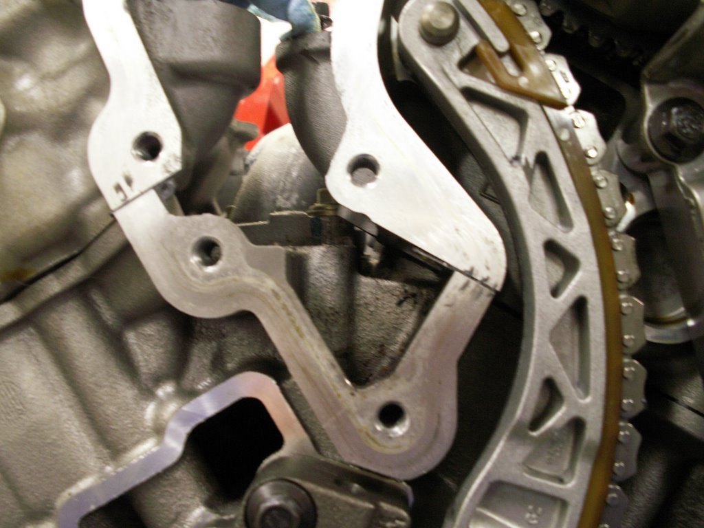
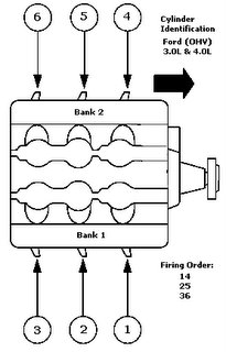
This is the mechanical process that I followed to discover the error. Keeping in mind that the actual sequencing of 6 pistions that come up to TDC on the power stroke is governed by the crankshaft and camshaft designs and cuts, one can easily validate firing order (1, 4, 2, 5, 3, 6), at least by pattern even if you didn't know the correct numbering sequence. With the camshafts exposed and plugs removed, I found a timing mark on the harmonic pulley on the front of the engine. Additionally, there is a TDC timing mark located on the front timing cover. Putting these two timing marks in alignment will put the #1 cylinder either on TDC of the power stroke or TDC of the intake stroke. This can be easily verified by viewing the camshafts on both banks and finding the cylinder that had both intakes and exhaust valves closed. 2 cylinders will be at TDC (#1 and #6), but only one of these 2 will have intake and exhaust valves closed. One will be at TDC of the compression stroke and the other will be at TDC of the intake stroke. From that point, each 120° rotation of the crankshaft will present the NEXT cylinder at TDC of the power stroke. If you know the firing order is 1, 4, 2, 5, 3, 6, then you've just numbered the cylinders automatically without knowing that spec. When I did this, it matched the JTIS spec of the S-Type 2002 MY and earlier - the X spec in JTIS is wrong.

Well, enough of that. Let's switch topics to valve shimming. Since my project engine was 15K miles old when I acquired it, I thought it would be good information for all to take the valve shim readings, and then publish FYI. Keep in mind that Jaguar does not specify a valve clearance check in any service materials. Here is a picture of the top of the engine with valve covers removed.

Essentially, you are rotating the crankshaft (clockwise always, of course - NEVER anticlockwise on a Duratec!!) sequentially, according to firing order until each set of intake and exhaust cam lobes appear in orientation 180° off the shim. Then measurements are made using feeler gauges in .001" increments, and results recorded. In the picture below, see a close up of the left bank. The lower cam is the exhaust cam and the upper cam is intake. In this picture, the exhaust valve pair shown on the left end of the exhaust cam is in position for the clearance check. This is the #4 cylinder. The intake valve pair on the far right of the intake cam is in position for check as well.

Here is a table showing the results using the new cylinder numbering sequence, OR, the S-Type sequence as shown in JTIS.

First theory about valve shimming: A gap between the valve stem and cam lobe is important because metal expands when it is hot. It is also essential that valves close completely on the compression stroke, otherwise compression could not be maintained. If no gap existed between the valve stems and the lowest landings on the cam shaft (zero clearance), then when the valves, shims, buckets, and cam lobes heated up and expanded with engine temp, the valves wouldn't close completely. So a gap of some specification is necessary.

Second theory: as an engine "breaks in", valves tend to "seat" themselves in the head. When this happens, an initial shim clearance will be reduced or closed. So the theory is: shim clearance will tend to decrease instead of increase.

Third theory: Exhaust valves get hotter than intake valves and thus expand more. This is because the intake valves are always receiving a cooling injection of air/fuel mixture that the exhaust valves don't receive, but the exhaust valves are constantly exposed to the hottest of spent gasses that the intakes don't receive. Conclusion: If the valve trains of the intake/exhaust are the same basic design, lengths and thicknesses, the exhaust clearances need to be more than the intakes.

Now for the forensic analysis: Refer to the readings in the table above, keeping in mind that this engine has only 15K miles on it. I am seriously concerned about two intake valves, of the pairs from the #1 and the #2 cylinders. These 2 gaps (.004"), highlighted in red, are half the gaps of all other intake valves. Coincidentally, these valves are located on the back bank (right bank) located by the firewall. If you recall previous concerns I've had in discussions regarding the exhaust and catalytic layout on the back or right bank, this cat is positioned horizontally and a fuller effect of heat dissapation is transferred to the engine head/block on the right side than on the left where the cat is positioned vertically. In fact, note that, in general, all of the exhasut clearances on the back (right) bank are lower than the cooler running (outer) left bank. I'm especially concerned since there appears to be no maintenance requirements or specifications given for valve clearance in JTIS or service, just a requirement to check them if the technician is working on other issues and it is convenient to do so. Make me want to strip down my 2.5L in my Sport with 35K miles on the clock. BTW, all other valve clearance readings appear to be normal and consistent.

The JTIS specs are (converted to inches):

Intake - .007 to .009"

Exhaust - .013 to .015"

Needless to say, I'll restore these two intake valves to .008" clearance before final assembly occurs sometime in the distant future.

Well, enough for this posting. Hope it's been informative and educational. I need to give serious consideration to some general direction now as too much more disassembly gets very expensive in terms of replaceable service items - gaskets, replacement bolts, etc. Additionally, if I decide to go in the direction of just a 3.0L replacement for my 2.5L, I'd rather not disturb basic factory sub-assemblies like heads, bedplate, etc.

Tuesday, January 03, 2006

Motor Project # 5 - Changing Plugs

From Steve Hannes - This project is meant to educate. NOTE of DISCLAIMER: THE FOLLOWING INFORMATION IS WRITTEN USING PROCEDURES DESCRIBED IN THE MANUFACTURER'S MATERIALS AND BASED ON MY OWN NUMEROUS YEARS' HANDS-ON AUTOMOTIVE EXPERIENCE. BE AWARE THAT BY USING THESE INSTRUCTIONS YOU AGREE TO HOLD ME (STEVE HANNES) HARMLESS FROM ANY AND ALL PERSONAL INJURIES, AND ANY AND ALL PROPERTY DAMAGE THAT MIGHT RESULT. THE USER OF THESE INSTRUCTIONS ACCEPTS ALL RESPONSIBILITIES FOR PERSONAL INJURY AND PROPERTY DAMAGES. THE FOLLOWING INSTRUCTIONS ARE ACCURATE TO THE BEST OF MY KNOWLEDGE. I HEREBY ACCEPT NO RESPONSIBILITY OR LIABILITIES FOR ANY ERRORS OR OMISSIONS. This project should only be taken on by a person with intermediate or higher mechanical experience - NOT FOR BEGINNERS! This procedure is the same for the 2.5L or the 3.0L V-6 Duratec used in the Jaguar X-Type series, all manufacturing years to date. Many X-Type owners like to perform simpler maintenance tasks such as spark plug replacement. On the X-Type, that is not the simple task as anyone with an X knows. The V-6 transverse design puts the right hand bank in the back of the engine bay facing the firewall, and the design of the multi-geometry intake manifold places it hovering directly over the RH cam cover. To put it succinctly, lots of disassembly of non-related parts must be done, then replaced in order to change all six spark plugs. In addition, some gaskets are recommended to be replaced to maintain the integrity of the vacuum in the intake system. Half way into this procedure you'll be exposing your engine to imminent danger!!! Because the intake ports will be exposed and you'll be leaning over, reaching over these ports with various tools and small hardware. The chances are VERY good that you'll drop something down a port and that could be fatal if you weren't aware or were unable to retrieve. So, the very first precaution is to cover the entire fuel injection plenum (lower intake assembly) with pieces of stiff cardboard, cut to size, once the upper intake manifold is removed. I'll give the dimensions of the cardboard below so that you can cut this in advance. OK - first things first. Let's make sure that you have everything that you'll need before beginning this task. Assuming that you have adequate tools (all bolts and mounting hardware on the X engine are metric), I'll only list parts and special items. If you follow my process, you'll need the following (all shown in pic):
  1. Set (6) upper intake manifold gaskets.
  2. One throttle body gasket.
  3. Set (6) spark plugs of your choice.
  4. Anti-seize compound
  5. Two pieces of cardboard 2"x12"
  6. One piece 6" (approx) of 3/8 id fuel line.

I won't get in to discussions about spark plug types. My own opinion - I'm not one for exotic plugs and I only like using what the manufacturer put in from the factory. So, it's your choice. The plugs in my 3.0L engine are a factory #, and appear to be autolite and are definitely a platinum plug. JTIS specifies part # XW4E12405. Autolite's cross over double platinum plug number is: APP605. JTIS gap specification is 0.051" to 0.057".

The gaskets that I've specified are recommended in JTIS to be replaced if they are removed. The 6" piece of fuel line is a special tool that you will use to install the new plugs (very important!). The two pieces of cardboard are like insurance policies. You'll use them to protect your precious engine against yourself - more to come.

OK - Let's begin at the beginning. If you open your hood and stand in front at the grille, your project should lay before you and look something like the picture here. If your engine looks substantially different than the picture, then you're working on the wrong car!

Of course we will be removing three plugs each on two engine banks. The front bank (left bank) is right in front of you. One of the three plugs can barely be seen to the left of the air cleaner. The other three are located in the back bank (right bank) located underneath the intake manifold and close to the firewall - and NO there are no shortcuts, the intake manifold must be removed to get to those plugs. So, let's begin:

  1. JTIS recommends disconnecting the battery. This is a good idea whenever you are unplugging connections to the ECM and we'll be doing that here.
  2. Remove the entire air cleaner. The cover, the filter and the lower box. Hardware should be intuitively obvious.
  3. Remove the ribbed rubber hose connector to the throttle body. Disconnect only one end, the throttle body end, and leave the air filter end fastened.
  4. Remove the black plastic air baffle past the air cleaner.
  5. Remove the Positive Crankcase Vent tube that connects the air filter to the intake manifold (just slips off the intake manifold).
  6. Now the front (left bank) three plug coils should be exposed.
  7. Continue removing the the intake manifold by removing the sensor connectors to the (2) tuning valves and the (1) manifold absolute pressure sensor. Look at the picture of the manifold here. This pic shows the black tuning valves on the far right. The manifold pressure sensor is the black sensor shown on the lower intake rail closer to the tuning valves. All three of these connectors use a timing tooth so they cannot be plugged in backwards. The all have release tabs that must be be pinched to remove.
  8. Now let's remove vacuum connections. There are three. Use the same photo and note the two holes, one on the lower rail and one at the junction of upper and lower rail. These connections can be removed by pressing down on the retaining ring then lifting the vacuum hose out. If you're at all in doubt about how to remove these, DO NOT force them. Instead disconnect the other ends. One is the vacuum feed to the power brake. The other hose has a convenient connector with press/release tabs much like the electrical connectors.
  9. That takes care of two of the three vacuum lines, now for the third. It is located on the back of the intake manifold and cannot be seen. In fact this line and four hardware screws must be removed (and replaced) using tactile skills. Use the picture here. It is a photo of the back of the manifold. See the fitting position marked VACUUM.
  10. Now let's remove or loosen the blind hardware. There are four hex head screws numbered in the picture. All take a 10mm hex socket or box wrench. The first two numbered #1 and #2 simply hold the RH main ECM harness branch in place. These two screws only need to be LOOSENED not removed as the holes in the harness bracket are open slotted. Screws #3 & #4 must be removed completely. They are mounting tabs. #3 cannot be seen, #4 can be seen just below and behind the throttle body.
  11. Now remove the four bolts (10mm hex socket) that hold the throttle body on to the intake manifold. You will mechanically disconnect the throttle body, but not disconnect any other electrical or coolant connections. The throttle body will just float in position when you remove the intake manifold. By doing it this way, you save several steps e.g.: draining the radiator, removing coolant lines to the throttle body, etc. NOTE/CAUTION: Do not attempt to clean the throttle body. The bore and the throttle plate have a special coating applied during manufacture which should not be removed.
  12. Now, let's remove the final six hex head bolts that hold the intake manifold in place. Look at the pic here and you'll see the manifold upside down and the six mounting positions will be obvious. It is IMPORTANT that you keep all six (6) bolts and rubber washers in their original orientation as they are different lengths and shapes.
  13. Once the intake manifold is removed, the lower intake manifold (with the six yellow neoprene intake gaskets) will be exposed. This is a dangerous time because if anything is dropped in an intake port, then you have a whole lot more work to do and not covered in this procedure. As a precaution, use the two precut pieces of cardboard to cover the intake ports as you begin to remove/replace coils and plugs. I've provided a picture of the lower intake port off the engine with one of the two cardboard pieces in place. You will NOT be removing this lower manifold.
  14. Now all six plug/coils are exposed so the plugs can be changed.
  15. Each coil is held in place with a hex head screw. Remove the screw, unplug the coil and remove it using a gentle twisting motion.
  16. It is IMPORTANT that you work in extreme cleanliness at this point. There are no flushing channels anywhere in the plug socket and you want to make sure that no debris of any kind gets in to the plug wells. They should be clean as they are protected by the coil seals. I still use a household vacuum cleaner with hose attachment and suck out anything out from all six wells before removing the spark plugs.
  17. After cleaning, use a 5/8 spark plug socket (with a rubber insert) on a 3/8 drive extension/ratchet and remove each plug.
  18. With all of the plugs out, it is a good practice to take note of the burn evidence on each plug. Lots can be told from this. I won't cover it here, but a quick web search can produce colored charts of different burn patterns with explanations.
  19. Now prepare the new plugs. Check the gap against the 0.051" to 0.057" gap requirement. The Autolite plugs should be correct already. It is a good practice to lean towards the lower measurement. In fact, Autolite specs say the APP605 comes with a 0.050 gap. That is good and I'd leave it as plug gaps will widen as they wear.
  20. This is where you'll use the anti-seize compound. Place a SMALL amount on the thread body of each plug and distribute around the circumference. Anti-seize compound is important wherever dissimilar metals (aluminum and steel) come into contact. Different metals can actually cold weld together over time because of chemical reaction. If you've had a frozen alloy wheel to your steel wheel hub, then you know what I mean. BTW - I use anti-seize compound of my wheel hubs too.
  21. Now take the 6" piece of 3/8" id fuel line and force it over the porcelain tip of the first plug. This hose is a special installation tool as your spark plug socket will not release when you install the plug.
  22. Use the hose with spark plug attached and hand thread the new plug in place (times 6). Then take a 5/8 spark plug socket with the rubber core OUT!! and tighten each plug to 11 ft. lbs.
  23. From here on, all is replace/reinstall. First place all six coils back in position and fix with their mounting screws. Plug in all six coils to their respective harness connections.
  24. Next replace the six intake manifold gaskets with new ones. Also replace the blue neoprene gasket for the throttle body located in the intake manifold.
  25. Install the intake manifold. There is a tightening sequence that is important to follow. I'll diagram it below. Also, first HAND tighten each of the six bolts, in proper sequence, then snug with a 8mm socket/ratchet in sequence, then finally torque to 10 nm (89 in.lbs) in sequence.
  26. Here is the tightening diagram. Use it as you are standing in front of the car at the grille. The front row has four bolts, the back row has two. Each # is placed on the bolt position. Start with #1, finish with bolt #6.

___5______________________3

_______2____ 1____4____ 6

27. After the manifold is in place with the six primary bolts tightened to torque spec, then complete the assembly of the four screws in the blind spot, (2 hold the harness, 2 are mounting tabs).

28. Reconnect the electrical connectors, (2 to the tuning valves, 1 to the vacuum sensor), then reconnect the vacuum lines, (1 in the back, 2 on top) of the intake manifold.

29. Now remount the throttle body. Four (4) bolts using a 10mm hex socket. These are torqued to 10 nm (89 in.lbs.)

30. Everything past this point is accessory assembly (air cleaner, connections, PCV hose, battery connect, etc).

And that should do it! Simple. If you have any questions, use this forum for Q&A

In a future project posting I'll put the process together to change oxygen sensors (4 in total). In modern OBD II engine design, no other component plays a bigger role in engine performance, gas mileage, etc. than the O2 sensors. Today, these have fairly good extended lives; however, they do deteriorate over time, and some fail. I replace these in my own cars at 60,000 miles.

Enjoy!