Motor Project # 6 - At the Core
From Steve Hannes - This project is meant to inform and educate.
Well, I am getting to the core of disassembly now. I am down to block and heads, but still have the front timing cover in place. I thought because of the complexity of the double timing chain design, I'd cover disassembly of that in a separate post.
Here, I'll share a fresh set of photos and include some maintenance information regarding valve shimming. Knowing that my engine came out of a car with 15K miles on it, I've taken the valve shim gap readings and posted below. This might be helpful forensic information for you, as JTIS doesn't list any maintenance intervals on valve shims and, of course, I'm concerned about the readings I have on this low mileage engine.
I found a very serious mistake in JTIS regarding information about firing order and cylinder numbering scheme on the X-Type, see below. This is the JTIS service disk that most of us have acquired (somehow). At leasst one Jaguar master technician with whom I communicate has researched and newer specs show the correct firing order and cylinder numbering.
Interestingly, now that I am down to the core components, I am seeing the Ford logo (oval) stamped on EVERYTHING - heads, block, oil sump pickup, etc. Not that there's anything wrong with that! I also noted that the engine ID plate has Cleveland manufacturing plant on it - not unexpected. Jag probably receives the short block (or perhaps the entire long block) assembled from Cleveland, final assembles it, then assembles it into cars, and then finally ships it to the US. Quite a circuitous trip for an engine, especially ironic for owners of Xs and Ss in Cleveland.
How about a little discussion on V6 design?
The Duratec V6 is a 60° layout. This means that if you look at the front of the engine and use the crankshaft center as a focal point, the heads vector from this point at a 60° angle. V8 engines are a 90° design. 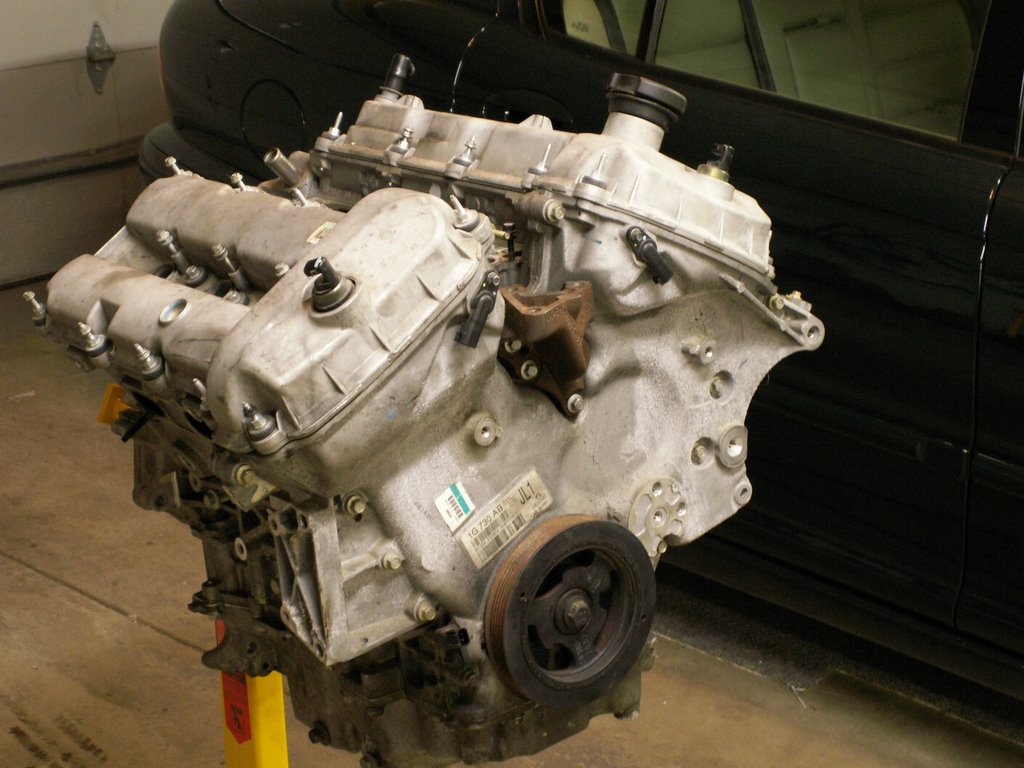 Use this picture of the duratec (Jag) 3.0L. Start with the bolt on the bottom pulley as the center point, then each head angle through the block creates a 60° angle.
From a geometric and manufacturing perspective, the V6 is the ultimate challenge. Think of it this way: take any other "V" engine layout (V8, V12, V16) and split it in half. The V8 gives you an inline 4; the V12 yields an inline 6; but the V6 yields an inline 3, an ODD number of cylinders. In an inline 4 or V8, a simple crankshaft design is used with crank pins at 180° angles. This means that there are always two pistons at top dead center and two at bottom dead center. If a 180° crankshaft were used in a V6, we would end up with a paired , then odd piston out at top/bottom dead centers. Then the firing order takes on a bizarre pattern (much like the Harley 45° V-Twin). Actually, in 1962 Buick introduced a V6 engine much like this, with an uneven firing order as related to crankshaft rotation. This was an unsuccessful venture and Buick dropped the design after a few years. I've had the pleasure of tuning up a couple of those in the late sixties; the cam cut in the distributor used to open/close the mechanical points was asymmetrical.
So, the answer to perfect balance on a V6 is a crankshaft with 3 crank pin pairs at 120° angles. And it's much more complex than that because each crank pin is actually offset. This is the crankshaft configuration used in the Duratec V6. Until recently, a crankshaft design like this was impossible to manufacture.
A V6 is not a perfectly balanced engine and benefits from some counterbalancing and harmonic damping. The optimal angle to minimize vibrations in the V6 is 60°, and this is commonly used. The most common 60° V6s were built by Ford European subsidiaries: Essex V6, Cologne V6 and the more recent Duratec V6. The Alfa-Romeo V6 is also common.
Let's take a look at where I am in disassembly.
Use this picture of the duratec (Jag) 3.0L. Start with the bolt on the bottom pulley as the center point, then each head angle through the block creates a 60° angle.
From a geometric and manufacturing perspective, the V6 is the ultimate challenge. Think of it this way: take any other "V" engine layout (V8, V12, V16) and split it in half. The V8 gives you an inline 4; the V12 yields an inline 6; but the V6 yields an inline 3, an ODD number of cylinders. In an inline 4 or V8, a simple crankshaft design is used with crank pins at 180° angles. This means that there are always two pistons at top dead center and two at bottom dead center. If a 180° crankshaft were used in a V6, we would end up with a paired , then odd piston out at top/bottom dead centers. Then the firing order takes on a bizarre pattern (much like the Harley 45° V-Twin). Actually, in 1962 Buick introduced a V6 engine much like this, with an uneven firing order as related to crankshaft rotation. This was an unsuccessful venture and Buick dropped the design after a few years. I've had the pleasure of tuning up a couple of those in the late sixties; the cam cut in the distributor used to open/close the mechanical points was asymmetrical.
So, the answer to perfect balance on a V6 is a crankshaft with 3 crank pin pairs at 120° angles. And it's much more complex than that because each crank pin is actually offset. This is the crankshaft configuration used in the Duratec V6. Until recently, a crankshaft design like this was impossible to manufacture.
A V6 is not a perfectly balanced engine and benefits from some counterbalancing and harmonic damping. The optimal angle to minimize vibrations in the V6 is 60°, and this is commonly used. The most common 60° V6s were built by Ford European subsidiaries: Essex V6, Cologne V6 and the more recent Duratec V6. The Alfa-Romeo V6 is also common.
Let's take a look at where I am in disassembly.

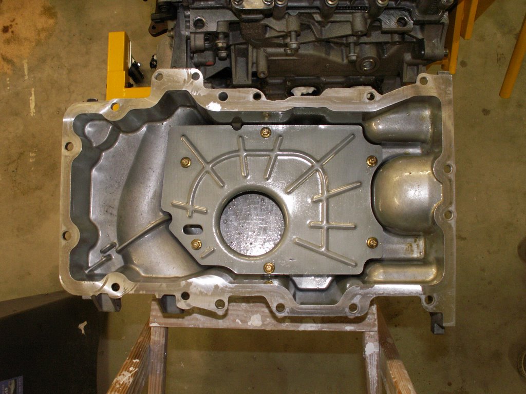 Here are two pictures of the bottom end. The first shows the engine inverted, with the oil pan removed. Note the baffle used and the oil sump pickup. These parts are all clearly stamped with the Ford Oval. The second picture shows the inside of the oil pan with a baffle plate raised about 3/4" from the floor of the pan. This helps to "settle" the oil in the pan so that the pickup is never sucking air.
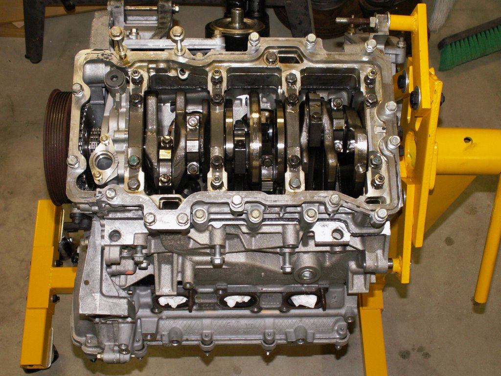
The below picture is of the engine inverted with the engine baffle removed. The crankshaft can be seen now. You can see the three pairs of crank pins: from the left, you see the #1 and #4 pistons; then on a 120° angle, the center pair (the #2 and #5 pins); and finally, on the right and another 120° apart, are the #3 and #6 pair.
Here are two pictures of the bottom end. The first shows the engine inverted, with the oil pan removed. Note the baffle used and the oil sump pickup. These parts are all clearly stamped with the Ford Oval. The second picture shows the inside of the oil pan with a baffle plate raised about 3/4" from the floor of the pan. This helps to "settle" the oil in the pan so that the pickup is never sucking air.
The below picture is of the engine inverted with the engine baffle removed. The crankshaft can be seen now. You can see the three pairs of crank pins: from the left, you see the #1 and #4 pistons; then on a 120° angle, the center pair (the #2 and #5 pins); and finally, on the right and another 120° apart, are the #3 and #6 pair.
 Now for some discussion on firing order and cylinder numbering: Although this won't serve the majority, I found a grievous error in JTIS in the cylinder numbering scheme listed for the X-Type. First, let's get firing order out of the way. In ANY publications I can find in Ford literature, the firing order on ALL Duratec V6s is 1, 4, 2, 5, 3, 6. This is very consistent and I accept that as fact. Now, the firing order needs to correspond with a cylinder numbering scheme.
JTIS (the CDs floating around on the web) lists the cylinder order as follows:
Looking from the rear of the engine, the left bank is numbered 6, 4, 2; the right bank is numbered 5, 3, 1. with a firing order (on all 3 V6 engines) of 1, 4, 2, 5, 3, 6. This is WRONG, WRONG, WRONG!!! as senator Byrd would put it. The corect firing order for this cylinder numbering sequence is: 1, 2, 3, 4, 5, 6. I know because I used some very basic mechanical principles to test/validate the firing order and cylinder numbering discussed below. BTW, after my own mechanical validation and "renumbering" of the cylinders, I researched the JTIS specs for the S-Type 3.0L before MY 2002 and JTIS lists the firing order of the 3.0L as: From the driver's seat, the Left Bank is 4, 5, 6; and the Right Bank is 1, 2, 3. This follows the generic numbering and firing order of all other Duratecs, so I am going to use them frem here on. It just suite me as I can cross info with other Ford owners that are doing performance enhancements. But, frankly, it makes no difference which sequence you use as long as the firing orders match these two options:
Now for some discussion on firing order and cylinder numbering: Although this won't serve the majority, I found a grievous error in JTIS in the cylinder numbering scheme listed for the X-Type. First, let's get firing order out of the way. In ANY publications I can find in Ford literature, the firing order on ALL Duratec V6s is 1, 4, 2, 5, 3, 6. This is very consistent and I accept that as fact. Now, the firing order needs to correspond with a cylinder numbering scheme.
JTIS (the CDs floating around on the web) lists the cylinder order as follows:
Looking from the rear of the engine, the left bank is numbered 6, 4, 2; the right bank is numbered 5, 3, 1. with a firing order (on all 3 V6 engines) of 1, 4, 2, 5, 3, 6. This is WRONG, WRONG, WRONG!!! as senator Byrd would put it. The corect firing order for this cylinder numbering sequence is: 1, 2, 3, 4, 5, 6. I know because I used some very basic mechanical principles to test/validate the firing order and cylinder numbering discussed below. BTW, after my own mechanical validation and "renumbering" of the cylinders, I researched the JTIS specs for the S-Type 3.0L before MY 2002 and JTIS lists the firing order of the 3.0L as: From the driver's seat, the Left Bank is 4, 5, 6; and the Right Bank is 1, 2, 3. This follows the generic numbering and firing order of all other Duratecs, so I am going to use them frem here on. It just suite me as I can cross info with other Ford owners that are doing performance enhancements. But, frankly, it makes no difference which sequence you use as long as the firing orders match these two options:
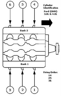
Left 4, 5, 6; Right 1, 2, 3 - Firing order 1, 4, 2, 5, 3, 6
OR
Left 2, 4, 6; Right 1, 3, 5 - firing order 1, 2, 3, 4, 5, 6
Here is a diagram of firing order and cylinder numbering for any generic duratec V6 and the one I will use:
 This is the mechanical process that I followed to discover the error. Keeping in mind that the actual sequencing of 6 pistions that come up to TDC on the power stroke is governed by the crankshaft and camshaft designs and cuts, one can easily validate firing order (1, 4, 2, 5, 3, 6), at least by pattern even if you didn't know the correct numbering sequence. With the camshafts exposed and plugs removed, I found a timing mark on the harmonic pulley on the front of the engine. Additionally, there is a TDC timing mark located on the front timing cover. Putting these two timing marks in alignment will put the #1 cylinder either on TDC of the power stroke or TDC of the intake stroke. This can be easily verified by viewing the camshafts on both banks and finding the cylinder that had both intakes and exhaust valves closed. 2 cylinders will be at TDC (#1 and #6), but only one of these 2 will have intake and exhaust valves closed. One will be at TDC of the compression stroke and the other will be at TDC of the intake stroke. From that point, each 120° rotation of the crankshaft will present the NEXT cylinder at TDC of the power stroke. If you know the firing order is 1, 4, 2, 5, 3, 6, then you've just numbered the cylinders automatically without knowing that spec. When I did this, it matched the JTIS spec of the S-Type 2002 MY and earlier - the X spec in JTIS is wrong.
Well, enough of that. Let's switch topics to valve shimming. Since my project engine was 15K miles old when I acquired it, I thought it would be good information for all to take the valve shim readings, and then publish FYI. Keep in mind that Jaguar does not specify a valve clearance check in any service materials. Here is a picture of the top of the engine with valve covers removed.

Essentially, you are rotating the crankshaft (clockwise always, of course - NEVER anticlockwise on a Duratec!!) sequentially, according to firing order until each set of intake and exhaust cam lobes appear in orientation 180° off the shim. Then measurements are made using feeler gauges in .001" increments, and results recorded. In the picture below, see a close up of the left bank. The lower cam is the exhaust cam and the upper cam is intake. In this picture, the exhaust valve pair shown on the left end of the exhaust cam is in position for the clearance check. This is the #4 cylinder. The intake valve pair on the far right of the intake cam is in position for check as well.

Here is a table showing the results using the new cylinder numbering sequence, OR, the S-Type sequence as shown in JTIS. ![]()
First theory about valve shimming: A gap between the valve stem and cam lobe is important because metal expands when it is hot. It is also essential that valves close completely on the compression stroke, otherwise compression could not be maintained. If no gap existed between the valve stems and the lowest landings on the cam shaft (zero clearance), then when the valves, shims, buckets, and cam lobes heated up and expanded with engine temp, the valves wouldn't close completely. So a gap of some specification is necessary.
Second theory: as an engine "breaks in", valves tend to "seat" themselves in the head. When this happens, an initial shim clearance will be reduced or closed. So the theory is: shim clearance will tend to decrease instead of increase.
Third theory: Exhaust valves get hotter than intake valves and thus expand more. This is because the intake valves are always receiving a cooling injection of air/fuel mixture that the exhaust valves don't receive, but the exhaust valves are constantly exposed to the hottest of spent gasses that the intakes don't receive. Conclusion: If the valve trains of the intake/exhaust are the same basic design, lengths and thicknesses, the exhaust clearances need to be more than the intakes.
Now for the forensic analysis: Refer to the readings in the table above, keeping in mind that this engine has only 15K miles on it. I am seriously concerned about two intake valves, of the pairs from the #1 and the #2 cylinders. These 2 gaps (.004"), highlighted in red, are half the gaps of all other intake valves. Coincidentally, these valves are located on the back bank (right bank) located by the firewall. If you recall previous concerns I've had in discussions regarding the exhaust and catalytic layout on the back or right bank, this cat is positioned horizontally and a fuller effect of heat dissapation is transferred to the engine head/block on the right side than on the left where the cat is positioned vertically. In fact, note that, in general, all of the exhasut clearances on the back (right) bank are lower than the cooler running (outer) left bank. I'm especially concerned since there appears to be no maintenance requirements or specifications given for valve clearance in JTIS or service, just a requirement to check them if the technician is working on other issues and it is convenient to do so. Make me want to strip down my 2.5L in my Sport with 35K miles on the clock. BTW, all other valve clearance readings appear to be normal and consistent.
The JTIS specs are (converted to inches):
Intake - .007 to .009"
Exhaust - .013 to .015"
Needless to say, I'll restore these two intake valves to .008" clearance before final assembly occurs sometime in the distant future.
Well, enough for this posting. Hope it's been informative and educational. I need to give serious consideration to some general direction now as too much more disassembly gets very expensive in terms of replaceable service items - gaskets, replacement bolts, etc. Additionally, if I decide to go in the direction of just a 3.0L replacement for my 2.5L, I'd rather not disturb basic factory sub-assemblies like heads, bedplate, etc.
posted by skhannes at 5:45 AM
![]()
![]()

0 Comments:
Post a Comment
<< Home