Motor Project # 14 - Waiting to Exhale, the 1st Sequel
From Steve Hannes - This project is meant to inform, educate.
Click on any picture to enlarge; then F11.
This is a continuation of the first "Waiting to Exhale" project - Exhaust modifications. In this project I have taken two directions to modify and improve the exhaust end of the flow design on the 3.0L Duratec used in the Jaguar X-Type. I have the designs completed now in the physical past the exhaust manifolds. One takes the standard exhaust manifolds and replaces them with some generic Duratec manifolds that are more "header like" then will push the catalytic converters back to a single hi-flow unit past the crossovers and collector.
The second design consists of a full blown set of headers with the same configuration. Both of these designs will significantly improve the flow of the engine and will ultimately increase HP and torque. Pictures of stock exhaust, plus both mod options are included.
First, some theory about engine performance. I read many Jaguar and Duratec chat sites and it amazes me just how much mis-information is out there about engine performance, especially when some give opinion and try to lay it out as fact. One very popular line is: "Jaguar engineers have designed the Duratec for ultimate performance and no additional performance can be achieved." This is so very far from the truth.
Think of complete engine performance as a "three legged stool". The first leg is "power", the second leg is "fuel efficiency", the third leg is "emissions efficiency". As with a stool, the length of each leg impacts the other two if total balance is what I am seeking to achieve . If I design for maximum fuel efficiency (increase the length of the fuel efficiency leg), I will negatively affect the power and emissions legs; design for maximum power (measured in HP and torque), I'll negatively impact emissions and fuel efficiency. And, of course, design for maximum emissions efficiency and I'll negatively affect fuel and power. The influence these three legs have on each other is subject to the laws of Physics and are not governed by opinion, and even very unique engine designs are still limited by these laws.
In modern engine design must consider country regulatory requirements, etc., and the ultimate design is struck using a balance of all three legs, then optimizing each using innovative, creative ideas like VVT, multi-port intake, etc. With upcoming, more stringent emissions requirements, what was Jaguar's (and Ford's) design requirements for the Duratec engines? #1 priority was to maximize emissions efficiency to meet those future regulatory requirements, and a close second was fuel efficiency to meet other country requirements and customer demand. That means then maximum power was sacrificed! So, for those who think there is no power left on the table in the Duratec Jaguar design, think again!
Let's look at how Jaguar accomplished maximum emissions efficiency on the Duratec in the X-Type. But then we'll examine the trouble they got into, and how they solved some problems they created. Everyone knows what a catalytic converter is. It is a key component in "converting" partially consumed fuels coming from the combustion chamber to a more completely consumed chemical compound. A key component in making a cat work is heat. The hotter the cat, the more efficiently it does its job. On startup when cats are cold, they really don't work.
Jaguar took two high efficiency, compact catalytic converters and designed them to attach directly to the exhaust manifolds. This positions them very (unusually) close to the engine and causes them to heat up much more quickly and operate much hotter. Great for the emissions leg of our stool! But an adverse outcome of doing this was additional heat buildup surrounding the engine (and engine bay). This caused the engine oil temperature to run too hot, and damaging heat impact on various accessories like - power steering pump, steering rack, transfer case, to name a few. To compensate, engineers were forced to water cool the engine oil...yes, water cool! I've complained before about the overly complex coolant system, one branch of which provides for an inlet/outlet coolant line through a modified oil filter housing. Unfortunately, some of these additional coolant legs with rubber hoses will eventually fail on us, probably on the road.
So, as an additional benefit to changing the configuration of the exhaust system on the 3.0L project engine, I will be making other modifications to the coolant system to return to a more traditional oil filtration fixture, and I will be eliminating some of the heat shielding that will positively affect the engine bay temps in several locales. Ultimately, this will become an easier engine to field repair with a lot of the shielding gone.
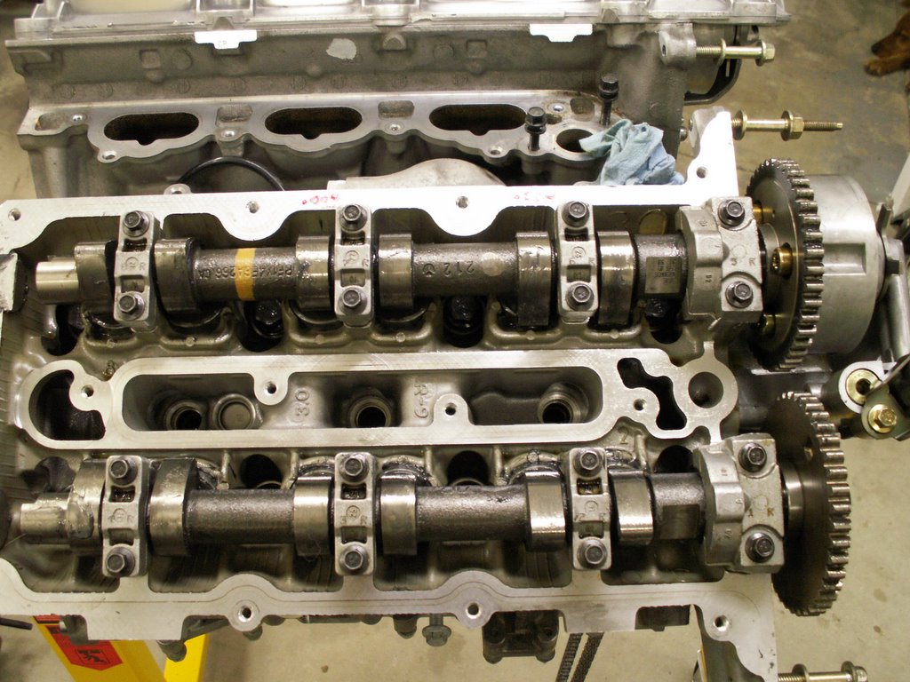
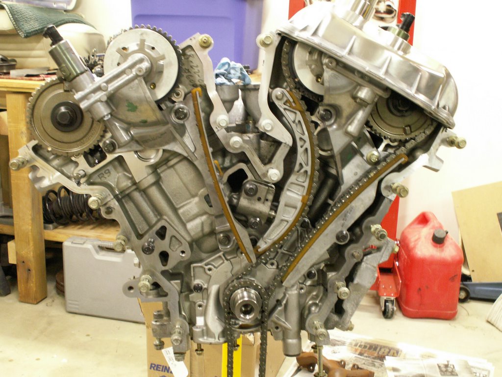
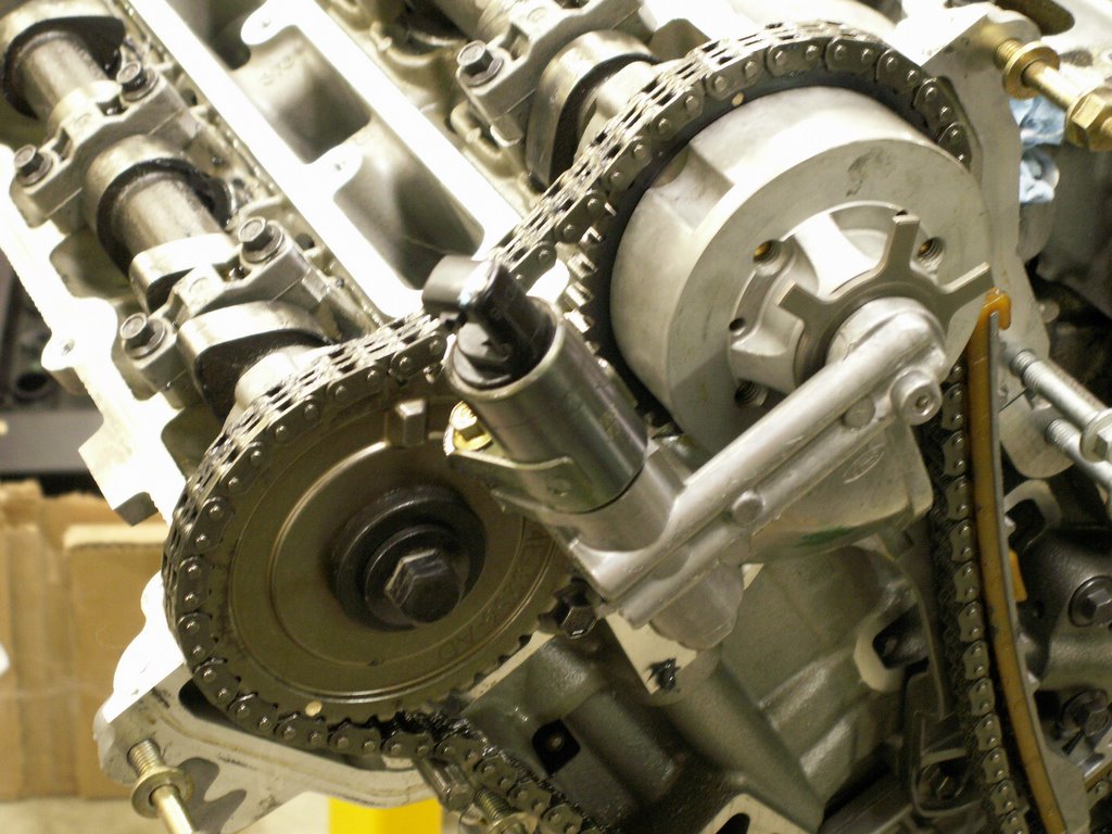
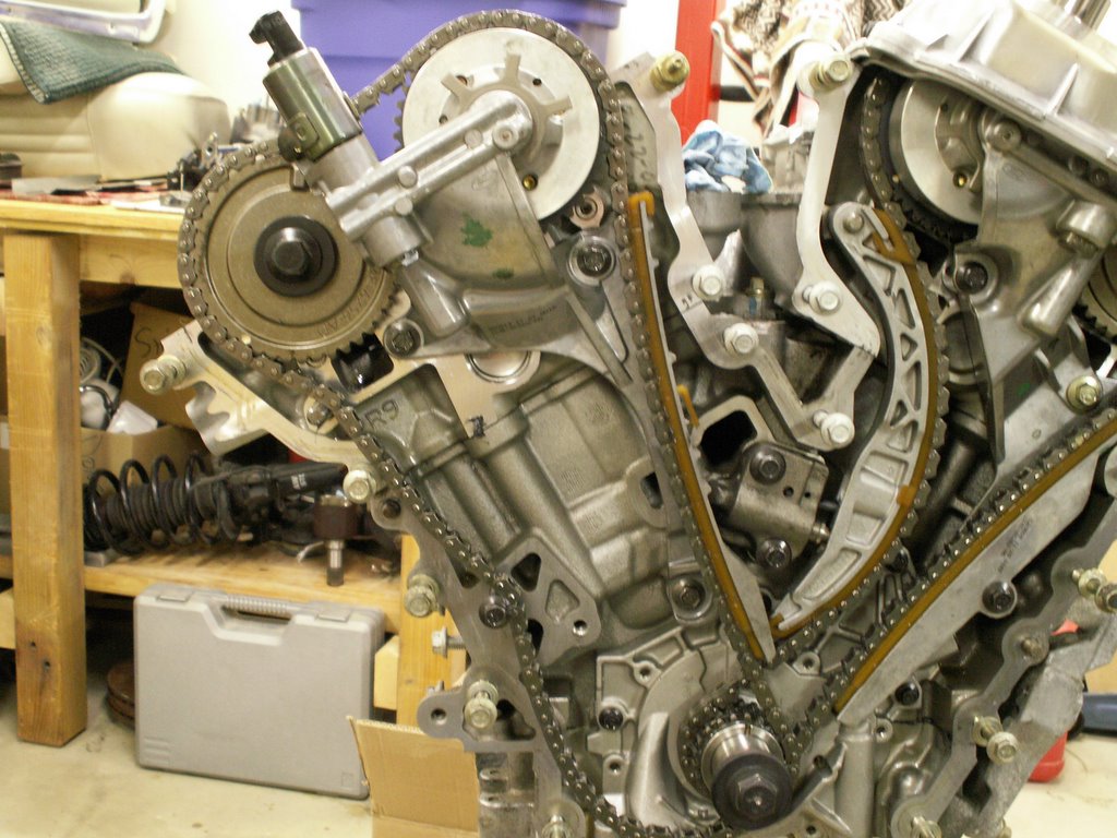
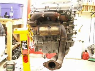
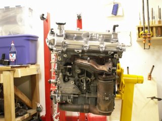
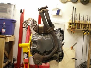
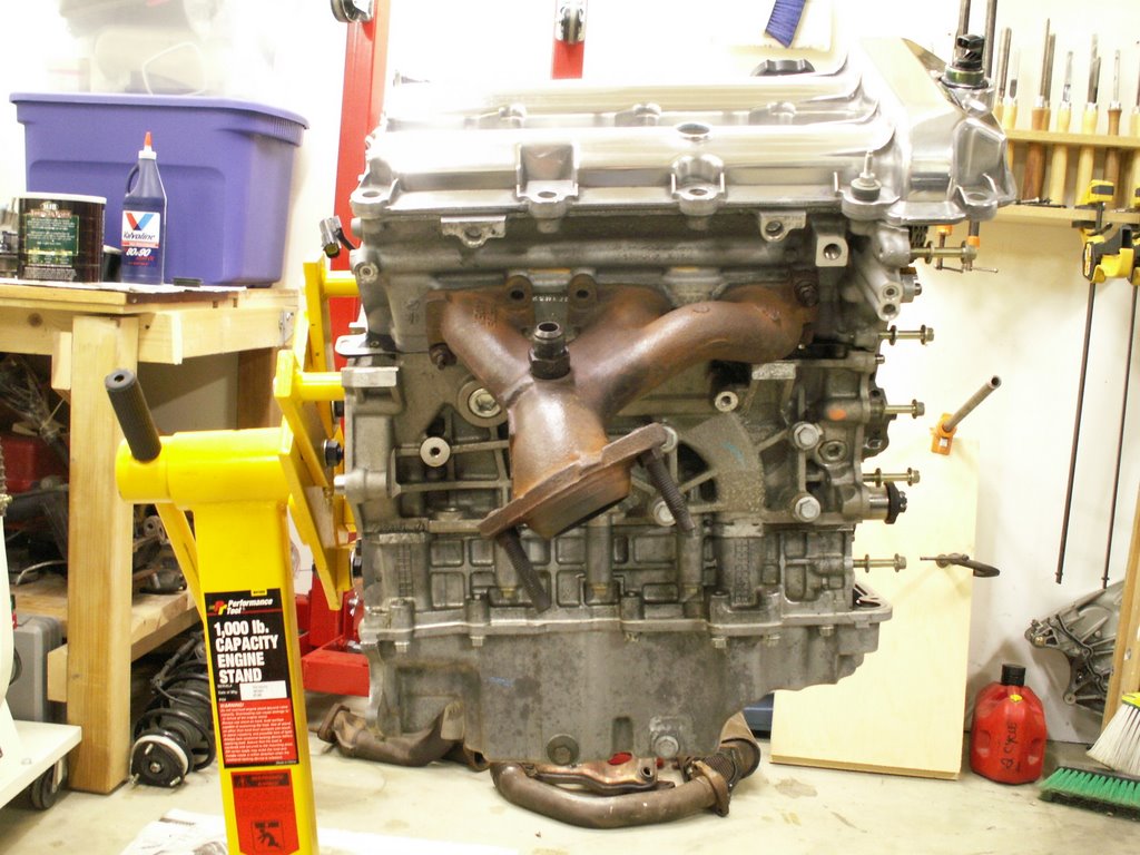
STOCK 3.0L Exhaust configuration as Jaguar designed it:
In these pictures I am showing the stock exhaust configuration. None of the heat shields are included so it is easy to get a look at the asymmetrical design and placements of the cats, high up in the exhaust stream.
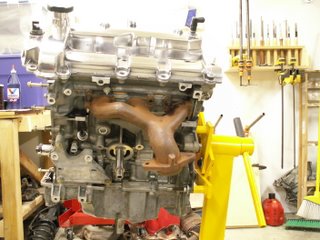
 OPTION I - Generic Duratec Exhaust Manifolds:
In the first option I am using a stock set of exhaust manifolds from a 1999 Taurus 3.0L. These are much more balanced left to right, have much better flow than the stock Jaguar versions and, when I get the crossovers and collectors completed, will have a cat back design located past the collector. It is intended to be a cost effective way of improving exhaust flow, and with less effort to accomplish the changeover.
OPTION I - Generic Duratec Exhaust Manifolds:
In the first option I am using a stock set of exhaust manifolds from a 1999 Taurus 3.0L. These are much more balanced left to right, have much better flow than the stock Jaguar versions and, when I get the crossovers and collectors completed, will have a cat back design located past the collector. It is intended to be a cost effective way of improving exhaust flow, and with less effort to accomplish the changeover.

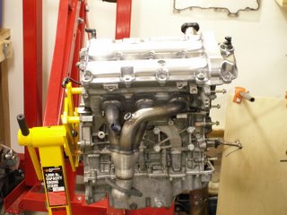
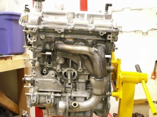
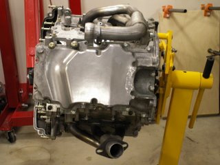
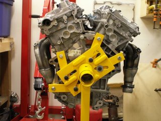
 OPTION II - Exhaust Header, Crossover, Collector, Single Hi-Flow Cat Solution:
Here are the same pics showing the full header solution. I'll mock the crossover and collector from corrugated tubing, then have them built in solid tubing at a muffler shop. Here too, the cat will be pushed back past the collector and will find itself under the chassis floor pan.
OPTION II - Exhaust Header, Crossover, Collector, Single Hi-Flow Cat Solution:
Here are the same pics showing the full header solution. I'll mock the crossover and collector from corrugated tubing, then have them built in solid tubing at a muffler shop. Here too, the cat will be pushed back past the collector and will find itself under the chassis floor pan.
 Now I will complete the fab mock ups to create the crossovers and collectors for both exhaust options. I've taken these pictures carefully and will use them in the first found of measurements for the mock ups, comparing the placements to the first set of pics showing the stock system. Then in final steps, I will use my X-Type to finish the layouts and fittings. These will be covered in future projects with the same project name.
Hope you find this project informative - enjoy!
Now I will complete the fab mock ups to create the crossovers and collectors for both exhaust options. I've taken these pictures carefully and will use them in the first found of measurements for the mock ups, comparing the placements to the first set of pics showing the stock system. Then in final steps, I will use my X-Type to finish the layouts and fittings. These will be covered in future projects with the same project name.
Hope you find this project informative - enjoy!


 OPTION I - Generic Duratec Exhaust Manifolds:
In the first option I am using a stock set of exhaust manifolds from a 1999 Taurus 3.0L. These are much more balanced left to right, have much better flow than the stock Jaguar versions and, when I get the crossovers and collectors completed, will have a cat back design located past the collector. It is intended to be a cost effective way of improving exhaust flow, and with less effort to accomplish the changeover.
OPTION I - Generic Duratec Exhaust Manifolds:
In the first option I am using a stock set of exhaust manifolds from a 1999 Taurus 3.0L. These are much more balanced left to right, have much better flow than the stock Jaguar versions and, when I get the crossovers and collectors completed, will have a cat back design located past the collector. It is intended to be a cost effective way of improving exhaust flow, and with less effort to accomplish the changeover.
 OPTION II - Exhaust Header, Crossover, Collector, Single Hi-Flow Cat Solution:
Here are the same pics showing the full header solution. I'll mock the crossover and collector from corrugated tubing, then have them built in solid tubing at a muffler shop. Here too, the cat will be pushed back past the collector and will find itself under the chassis floor pan.
OPTION II - Exhaust Header, Crossover, Collector, Single Hi-Flow Cat Solution:
Here are the same pics showing the full header solution. I'll mock the crossover and collector from corrugated tubing, then have them built in solid tubing at a muffler shop. Here too, the cat will be pushed back past the collector and will find itself under the chassis floor pan.


 Now I will complete the fab mock ups to create the crossovers and collectors for both exhaust options. I've taken these pictures carefully and will use them in the first found of measurements for the mock ups, comparing the placements to the first set of pics showing the stock system. Then in final steps, I will use my X-Type to finish the layouts and fittings. These will be covered in future projects with the same project name.
Hope you find this project informative - enjoy!
Now I will complete the fab mock ups to create the crossovers and collectors for both exhaust options. I've taken these pictures carefully and will use them in the first found of measurements for the mock ups, comparing the placements to the first set of pics showing the stock system. Then in final steps, I will use my X-Type to finish the layouts and fittings. These will be covered in future projects with the same project name.
Hope you find this project informative - enjoy!
posted by skhannes at 6:17 PM
0 comments
![]()
![]()