Motor Project # 10 - Just Breathe!
This project is provided by KARL WOLF and is meant to educate.
This project can be accomplished by someone with average to high mechanical skills - not for beginners.
Karl is an expert in many areas of modern automotive technologies. He has years of experience with intake/exhaust efficiency and port/head flow dynamics. He provides some simple, low cost techniques to improve intake flow dynamics on the X-Type intake manifold. These techniques will work on the 2.5L and the 3.0L V6 Duratecs produced by Jaguar.
Here's Karl:
The X Type motor is a very well designed, very efficient motor. As Steve has pointed out, the major areas that can be improved upon are the intake and exhaust systems. This procedure could easily be done when the manifold is off during a spark plug change.
This post will describe how to gain improvements in airflow thru the intake manifold. I will point out areas of concern and how to eliminate them. Keep in mind that the manifold in these pictures has less than 15k on it. Carbon builds up very quickly behind the throttle body which can hinder airflow. In another post I will detail how to SAFELY clean a coated throttle body. Jaguar coats these throttle bodies with a clearcoat to maximize air flow, but this surface is easily damaged or destroyed if you aren't aware.
Remember that the Jaguar intake design consists of two different intake tracks. These intake tracks can be switched back and forth through solenoid control valves and are selected (opened/closed) by the ECM under various RPM, load and engine temperature conditions to maiximze air flow and ultimately maximize engine torque.
The FIRST area for improvement.
Picture 1, the area directly behind the throttle body(click on any picture to enlarge it):
 As you can see through the throttle body port, there is a large (vertical) flat surface which separates the two runners. This area is directly behind the Throttle Body and is the first bottleneck. This area needs to be smoothed and brought to a point to allow a smooth transition from the TB to the two runners. The front angle should be biased/angled so that the left runner is more exposed. It has a shorter radius and inherently greater restriction.
Picture 2, improved port:
As you can see through the throttle body port, there is a large (vertical) flat surface which separates the two runners. This area is directly behind the Throttle Body and is the first bottleneck. This area needs to be smoothed and brought to a point to allow a smooth transition from the TB to the two runners. The front angle should be biased/angled so that the left runner is more exposed. It has a shorter radius and inherently greater restriction.
Picture 2, improved port: 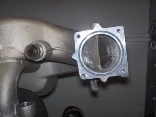 Smooth this area with a Dremel, drill, or die grinder and take out any internal lumps and casting slag. It needs to be relatively smooth but doesn’t have to be perfect. Refer to picture 1 and you will see that the area quickly becomes covered with carbon/oil residue. The oil residue comes from reminants of the PCV which utilizes the intake manifold as a crankcase breather.
The SECOND area for improvement.
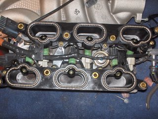
Picture 3, the intake runners:
Smooth this area with a Dremel, drill, or die grinder and take out any internal lumps and casting slag. It needs to be relatively smooth but doesn’t have to be perfect. Refer to picture 1 and you will see that the area quickly becomes covered with carbon/oil residue. The oil residue comes from reminants of the PCV which utilizes the intake manifold as a crankcase breather.
The SECOND area for improvement.
Picture 3, the intake runners:  In this picture the lower intake manifold (black plastic) is assembled to the upper manifold the way the engine would receive the assemblies, except it is turned upside down so that you can clearly see down the six oval ports as they flow to the intake valves. Note the six green fuel injectors in place.
As you can see, the aluminum intake runners are smaller than the oval ports in the black plastic lower intake manifold. This causes a restriction in the airflow capability of each cylinder. Attach the plastic lower manifold to the upper as shown here. Scribe a line around the inside of the plastic ports on ALL areas showing from the aluminum upper manifold. Separate the two manifolds and carefully remove the material from the aluminum ports until you come to the scribe marks. (NOTE: if you do not want to remove the lower manifold, acceptable results can be obtained by creating a template of the lower manifold ports. Use a thin piece of cardboard and carefully press it onto the lower ports one side at a time. Make sure you have the mounting points as a reference. Carefully cut out the ports on the pattern and transfer them to the upper manifold.) Work carefully and smooth the port transition into the manifold runner. The 80 grit sanding cylinders work best as they do not load up with the aluminum.
Picture 4, Improved ports:
You should be able to match the ports exactly to the lower manifold. Look through each oval, compare to the picture above and note the aluminum landings are now gone and these upper intake ports now match the lower (black plastic) ports.
In this picture the lower intake manifold (black plastic) is assembled to the upper manifold the way the engine would receive the assemblies, except it is turned upside down so that you can clearly see down the six oval ports as they flow to the intake valves. Note the six green fuel injectors in place.
As you can see, the aluminum intake runners are smaller than the oval ports in the black plastic lower intake manifold. This causes a restriction in the airflow capability of each cylinder. Attach the plastic lower manifold to the upper as shown here. Scribe a line around the inside of the plastic ports on ALL areas showing from the aluminum upper manifold. Separate the two manifolds and carefully remove the material from the aluminum ports until you come to the scribe marks. (NOTE: if you do not want to remove the lower manifold, acceptable results can be obtained by creating a template of the lower manifold ports. Use a thin piece of cardboard and carefully press it onto the lower ports one side at a time. Make sure you have the mounting points as a reference. Carefully cut out the ports on the pattern and transfer them to the upper manifold.) Work carefully and smooth the port transition into the manifold runner. The 80 grit sanding cylinders work best as they do not load up with the aluminum.
Picture 4, Improved ports:
You should be able to match the ports exactly to the lower manifold. Look through each oval, compare to the picture above and note the aluminum landings are now gone and these upper intake ports now match the lower (black plastic) ports.
 The THIRD area for improvement.
Picture 5, the manifold valves:
The THIRD area for improvement.
Picture 5, the manifold valves:
 This area requires the least work. Look for any casting areas where there is not a smooth transition from one area to another. I found a large area in the lower surface of the upper port. I also smoothed the left edge of the machined surfaces to enhance flow.
Picture 6, Improved port:
Thoroughly clean the inside of the manifold to remove all the aluminum filings. I first used air to blow out everything possible. I found that a large plastic storage bin filled with water and car wash detergent works great. Just make sure you remove the MAP sensor from the manifold before cleaning.
This area requires the least work. Look for any casting areas where there is not a smooth transition from one area to another. I found a large area in the lower surface of the upper port. I also smoothed the left edge of the machined surfaces to enhance flow.
Picture 6, Improved port:
Thoroughly clean the inside of the manifold to remove all the aluminum filings. I first used air to blow out everything possible. I found that a large plastic storage bin filled with water and car wash detergent works great. Just make sure you remove the MAP sensor from the manifold before cleaning. 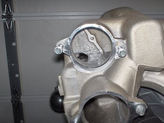 Conclusion:
How much additional power can you expect? The middle of winter in Chicago is not the best time to test this out. Experience tells me that these modifications should net about 10HP along with increased mileage. Cost? About $10 in supplies and 2 hours time.
Watch for future projects that test the manifold modifications. We'll look at the "other" end of the process too - the Exhaust end.
Enjoy.
Conclusion:
How much additional power can you expect? The middle of winter in Chicago is not the best time to test this out. Experience tells me that these modifications should net about 10HP along with increased mileage. Cost? About $10 in supplies and 2 hours time.
Watch for future projects that test the manifold modifications. We'll look at the "other" end of the process too - the Exhaust end.
Enjoy.
 As you can see through the throttle body port, there is a large (vertical) flat surface which separates the two runners. This area is directly behind the Throttle Body and is the first bottleneck. This area needs to be smoothed and brought to a point to allow a smooth transition from the TB to the two runners. The front angle should be biased/angled so that the left runner is more exposed. It has a shorter radius and inherently greater restriction.
Picture 2, improved port:
As you can see through the throttle body port, there is a large (vertical) flat surface which separates the two runners. This area is directly behind the Throttle Body and is the first bottleneck. This area needs to be smoothed and brought to a point to allow a smooth transition from the TB to the two runners. The front angle should be biased/angled so that the left runner is more exposed. It has a shorter radius and inherently greater restriction.
Picture 2, improved port: 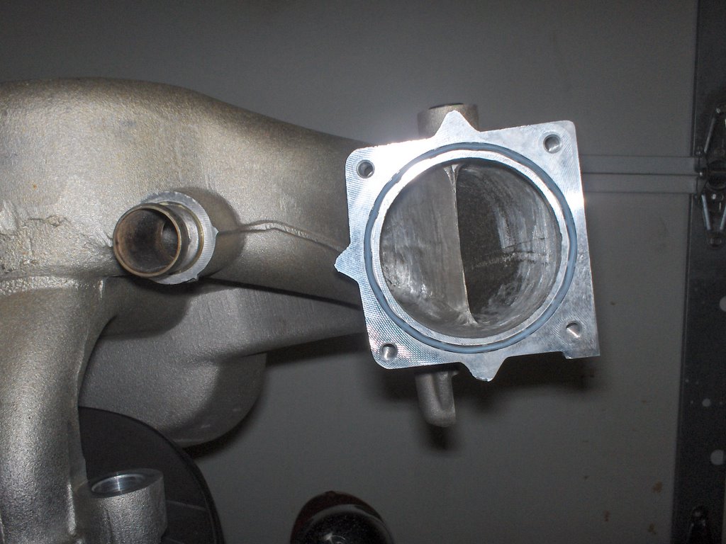 Smooth this area with a Dremel, drill, or die grinder and take out any internal lumps and casting slag. It needs to be relatively smooth but doesn’t have to be perfect. Refer to picture 1 and you will see that the area quickly becomes covered with carbon/oil residue. The oil residue comes from reminants of the PCV which utilizes the intake manifold as a crankcase breather.
The SECOND area for improvement.
Picture 3, the intake runners:
Smooth this area with a Dremel, drill, or die grinder and take out any internal lumps and casting slag. It needs to be relatively smooth but doesn’t have to be perfect. Refer to picture 1 and you will see that the area quickly becomes covered with carbon/oil residue. The oil residue comes from reminants of the PCV which utilizes the intake manifold as a crankcase breather.
The SECOND area for improvement.
Picture 3, the intake runners: 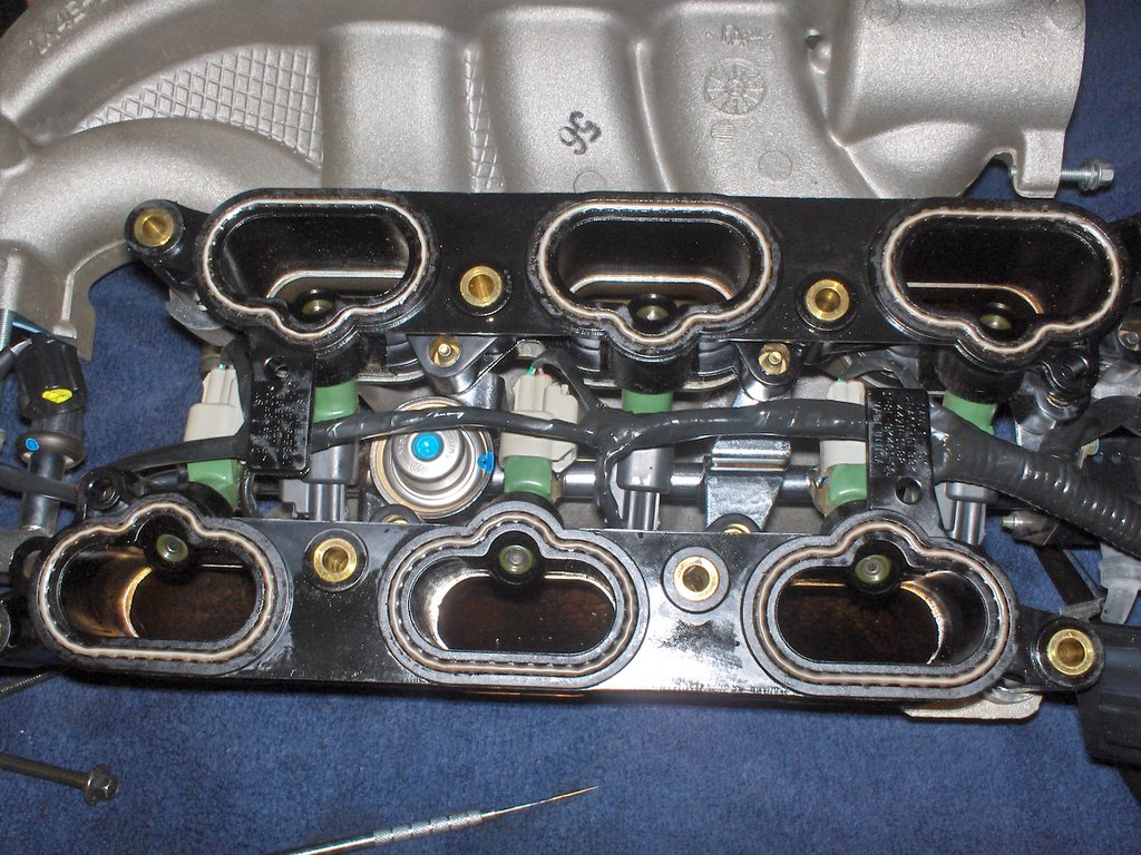 In this picture the lower intake manifold (black plastic) is assembled to the upper manifold the way the engine would receive the assemblies, except it is turned upside down so that you can clearly see down the six oval ports as they flow to the intake valves. Note the six green fuel injectors in place.
As you can see, the aluminum intake runners are smaller than the oval ports in the black plastic lower intake manifold. This causes a restriction in the airflow capability of each cylinder. Attach the plastic lower manifold to the upper as shown here. Scribe a line around the inside of the plastic ports on ALL areas showing from the aluminum upper manifold. Separate the two manifolds and carefully remove the material from the aluminum ports until you come to the scribe marks. (NOTE: if you do not want to remove the lower manifold, acceptable results can be obtained by creating a template of the lower manifold ports. Use a thin piece of cardboard and carefully press it onto the lower ports one side at a time. Make sure you have the mounting points as a reference. Carefully cut out the ports on the pattern and transfer them to the upper manifold.) Work carefully and smooth the port transition into the manifold runner. The 80 grit sanding cylinders work best as they do not load up with the aluminum.
Picture 4, Improved ports:
You should be able to match the ports exactly to the lower manifold. Look through each oval, compare to the picture above and note the aluminum landings are now gone and these upper intake ports now match the lower (black plastic) ports.
In this picture the lower intake manifold (black plastic) is assembled to the upper manifold the way the engine would receive the assemblies, except it is turned upside down so that you can clearly see down the six oval ports as they flow to the intake valves. Note the six green fuel injectors in place.
As you can see, the aluminum intake runners are smaller than the oval ports in the black plastic lower intake manifold. This causes a restriction in the airflow capability of each cylinder. Attach the plastic lower manifold to the upper as shown here. Scribe a line around the inside of the plastic ports on ALL areas showing from the aluminum upper manifold. Separate the two manifolds and carefully remove the material from the aluminum ports until you come to the scribe marks. (NOTE: if you do not want to remove the lower manifold, acceptable results can be obtained by creating a template of the lower manifold ports. Use a thin piece of cardboard and carefully press it onto the lower ports one side at a time. Make sure you have the mounting points as a reference. Carefully cut out the ports on the pattern and transfer them to the upper manifold.) Work carefully and smooth the port transition into the manifold runner. The 80 grit sanding cylinders work best as they do not load up with the aluminum.
Picture 4, Improved ports:
You should be able to match the ports exactly to the lower manifold. Look through each oval, compare to the picture above and note the aluminum landings are now gone and these upper intake ports now match the lower (black plastic) ports.
 The THIRD area for improvement.
Picture 5, the manifold valves:
The THIRD area for improvement.
Picture 5, the manifold valves:
 This area requires the least work. Look for any casting areas where there is not a smooth transition from one area to another. I found a large area in the lower surface of the upper port. I also smoothed the left edge of the machined surfaces to enhance flow.
Picture 6, Improved port:
Thoroughly clean the inside of the manifold to remove all the aluminum filings. I first used air to blow out everything possible. I found that a large plastic storage bin filled with water and car wash detergent works great. Just make sure you remove the MAP sensor from the manifold before cleaning.
This area requires the least work. Look for any casting areas where there is not a smooth transition from one area to another. I found a large area in the lower surface of the upper port. I also smoothed the left edge of the machined surfaces to enhance flow.
Picture 6, Improved port:
Thoroughly clean the inside of the manifold to remove all the aluminum filings. I first used air to blow out everything possible. I found that a large plastic storage bin filled with water and car wash detergent works great. Just make sure you remove the MAP sensor from the manifold before cleaning. 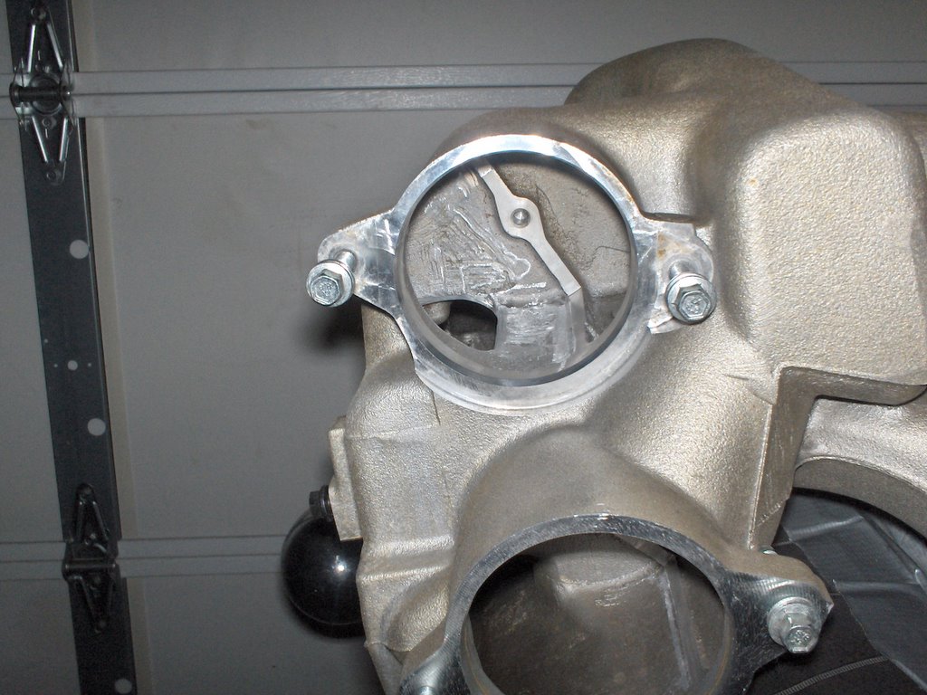 Conclusion:
How much additional power can you expect? The middle of winter in Chicago is not the best time to test this out. Experience tells me that these modifications should net about 10HP along with increased mileage. Cost? About $10 in supplies and 2 hours time.
Watch for future projects that test the manifold modifications. We'll look at the "other" end of the process too - the Exhaust end.
Enjoy.
Conclusion:
How much additional power can you expect? The middle of winter in Chicago is not the best time to test this out. Experience tells me that these modifications should net about 10HP along with increased mileage. Cost? About $10 in supplies and 2 hours time.
Watch for future projects that test the manifold modifications. We'll look at the "other" end of the process too - the Exhaust end.
Enjoy.
posted by skhannes at 12:30 PM
![]()
![]()

1 Comments:
I like the idea of cleaning up the port mismatch but if you noticed when you replaced the sparkplugs the upper intake "floats" around on the grommets. Without reference marks to be sure that the upper and lower manifolds are installed in the exact position they were in when the cleanup was done it may all be for naught. In fact you may be able to get a better port match just by aligning the 2 manifolds off of the engine and putting a few reference marks to realign them when they are reinstalled after a plug change. The cost would be zero and there would be no chance of metal that was hiding inside some hidden area of the manifold from scoring the cylinder walls.
Post a Comment
<< Home