Motor Project # 7 - Timing is Everything
 In this post I'll pursue those two valves and correct the clearances. I'll just cover what I need to get to those two shims. I'll put assembly in some future post; otherwise, this would take up a lot of space and pics.
The Jaguar Duratec head design is unique in its application for the X-Type. The 2.5L and 3.0L both use the same layout, except the valves are slightly larger in the 3.0L. This is a double overhead cam design with a mechanical valve train and not hydraulic as other Duratecs are. Jaguar designed a variable valve timing (VVT) feature and works by varying the cam positions of the intake cams only. Their positions change in relation to the position of the crankshaft and exhaust cams to optimize torque during the rpm range from idle to redline.
The system works using a hydraulic two-port pump design, fed with engine oil and pressure, and controlled by the ECM. The ECM sends a signal to the pumps to close one port, open the other to advance the intake cams to create the optimal combination of performance/fuel economy/emissions at certain places during the RPM/load range, then sends the opposite signal (close that port, open the first) to retard the intake cams.
These electric/hydraulic pumps (one for each intake cam) are VERY sensitive to oil viscosity, so it is important to use the "right" oil weight, otherwise, the VVT might not function even though the ECM sends signals to advance or retard. 5W 30 multi-grade is the best weight range for most driving conditions and tested to be the required weight by Jaguar. Note that the engine oil cap has 5W 30 printed on its top. If another weight oil is used in a Duratec the W should never be higher than 5W, so the only other option might be 0W 30.
Enough philosophy - let's get our hands dirty. If you remember from past posts, I have the Duratec torn down to expose the cams. It is down to the block and heads, but the timing cover was left in place. Here we'll remove the timing cover and timing chains so the intake cam can be removed, then we can finally reveal/remove the shim buckets. These shims on buckets control the valve clearance. They are a two piece design (bucket and shim). There is no way around using any special tool to depress the bucket and remove just the shim like so many other mechanical lifter DOHC designs, including other Jaguar engines. If someone has I'd like to hear from them.
So, first step is to remove the crankshaft pulley. There is a special Jaguar tool used to hold the pulley from turning anti-clockwise as the retaining bolt is broken loose. Remember, it is critical that the crankshaft only turn clockwise for two reasons - the timing chain tensioners can be damaged if they travel backwards and the journal bearings are specially ground to minimize wear in one direction. If the engine were to turn anti-clockwise, burrs might be created on the bearings - a true no, no.
I made my own special tool to hold the crank pulley using an old serpentine belt. Break the retaining bolt loose, then use a three legged gear puller to back the pulley off the crankshaft and key. After the pulley is removed, loosen and remove all of the bolts holding the timing cover in place. With all bolts out, the timing cover needs to be LIGHTLY tapped to break the gasket bonds. It's important to use something soft (such as a piece of wood) with a rubber mallet. Do not hit the cover with a hammer! Place the wood on a non-gasketed surface, then lightly tap the wood - Capish?
Here is a picture of the timing cover. It is a HUGE (and ugly), heavy aluminum casting. It will come with a crankshaft oil seal (that I will replace before reassembly), the cam position sensors, and the crankshaft position sensor. Integral to the casting are the entire mounting ears (brackets) for the alternator and the power steering pump. Be careful how you handle this piece with its bulk.
In this post I'll pursue those two valves and correct the clearances. I'll just cover what I need to get to those two shims. I'll put assembly in some future post; otherwise, this would take up a lot of space and pics.
The Jaguar Duratec head design is unique in its application for the X-Type. The 2.5L and 3.0L both use the same layout, except the valves are slightly larger in the 3.0L. This is a double overhead cam design with a mechanical valve train and not hydraulic as other Duratecs are. Jaguar designed a variable valve timing (VVT) feature and works by varying the cam positions of the intake cams only. Their positions change in relation to the position of the crankshaft and exhaust cams to optimize torque during the rpm range from idle to redline.
The system works using a hydraulic two-port pump design, fed with engine oil and pressure, and controlled by the ECM. The ECM sends a signal to the pumps to close one port, open the other to advance the intake cams to create the optimal combination of performance/fuel economy/emissions at certain places during the RPM/load range, then sends the opposite signal (close that port, open the first) to retard the intake cams.
These electric/hydraulic pumps (one for each intake cam) are VERY sensitive to oil viscosity, so it is important to use the "right" oil weight, otherwise, the VVT might not function even though the ECM sends signals to advance or retard. 5W 30 multi-grade is the best weight range for most driving conditions and tested to be the required weight by Jaguar. Note that the engine oil cap has 5W 30 printed on its top. If another weight oil is used in a Duratec the W should never be higher than 5W, so the only other option might be 0W 30.
Enough philosophy - let's get our hands dirty. If you remember from past posts, I have the Duratec torn down to expose the cams. It is down to the block and heads, but the timing cover was left in place. Here we'll remove the timing cover and timing chains so the intake cam can be removed, then we can finally reveal/remove the shim buckets. These shims on buckets control the valve clearance. They are a two piece design (bucket and shim). There is no way around using any special tool to depress the bucket and remove just the shim like so many other mechanical lifter DOHC designs, including other Jaguar engines. If someone has I'd like to hear from them.
So, first step is to remove the crankshaft pulley. There is a special Jaguar tool used to hold the pulley from turning anti-clockwise as the retaining bolt is broken loose. Remember, it is critical that the crankshaft only turn clockwise for two reasons - the timing chain tensioners can be damaged if they travel backwards and the journal bearings are specially ground to minimize wear in one direction. If the engine were to turn anti-clockwise, burrs might be created on the bearings - a true no, no.
I made my own special tool to hold the crank pulley using an old serpentine belt. Break the retaining bolt loose, then use a three legged gear puller to back the pulley off the crankshaft and key. After the pulley is removed, loosen and remove all of the bolts holding the timing cover in place. With all bolts out, the timing cover needs to be LIGHTLY tapped to break the gasket bonds. It's important to use something soft (such as a piece of wood) with a rubber mallet. Do not hit the cover with a hammer! Place the wood on a non-gasketed surface, then lightly tap the wood - Capish?
Here is a picture of the timing cover. It is a HUGE (and ugly), heavy aluminum casting. It will come with a crankshaft oil seal (that I will replace before reassembly), the cam position sensors, and the crankshaft position sensor. Integral to the casting are the entire mounting ears (brackets) for the alternator and the power steering pump. Be careful how you handle this piece with its bulk.  Some points of interest - there are three formed gaskets used to seal the timing cover. Keep in mind that oil is flowing behind this cover during engine operation. I've put the gaskets in place and they can be seen in this picture. Along with these gaskets, a silicone gasket material must be used in 6 places (2 places each gasket) as these three formed rubber gaskets cross no less than six part lines on the engine assembly - four places at the head/block lines and 2 places at the bedplate lines. I'll include two pictures at the end of this post with closeups of part lines. The fourth seal is the crankshaft seal. It can be seen in place. Part of the oil pan gasket (two oil pan bolts shown in place) and the valve cover gaskets
are sealed to the timing cover after its assembly.
Some points of interest - there are three formed gaskets used to seal the timing cover. Keep in mind that oil is flowing behind this cover during engine operation. I've put the gaskets in place and they can be seen in this picture. Along with these gaskets, a silicone gasket material must be used in 6 places (2 places each gasket) as these three formed rubber gaskets cross no less than six part lines on the engine assembly - four places at the head/block lines and 2 places at the bedplate lines. I'll include two pictures at the end of this post with closeups of part lines. The fourth seal is the crankshaft seal. It can be seen in place. Part of the oil pan gasket (two oil pan bolts shown in place) and the valve cover gaskets
are sealed to the timing cover after its assembly.
On the lower righthand corner of the picture, I've included the crankshaft position gear. It sits freely on the crankshaft behind the timing cover and is held in place by the crankshaft pulley. Take a close look at this gear. It has two keyway notches and, yes, it CAN be installed incorrectly. Make sure the keyway notch that is used on the keyway is the one with the missing tooth - Capish?. You can see the black CP Sensor coming through the timing cover. It's a magnetic pickup and reads the teeth from the CP gear. The missing tooth tells the ECM the engine is at TDC.
OK, let's see what we've revealed by removing the timing cover. The cam timing chains are now visible and can be removed. For this project, I will only remove the timing chain for the right bank (left side bank in the picture) where my two "troubled" valves are located. Luckily, the RH bank is the outer timing chain so I can leave the LH bank in place for this project.  In this picture you can view the two intake cam electro-hydraulic pumps with the ECM sensor connectors in place. The tops of these can be seen as coming through the valve covers on an assembled running engine. The double timing chain design is a very simple, easy to time layout. Let's focus at only one side at a time. Going clockwise (always clockwise on this engine) a chain runs from the crankshaft over a curved chain track. This is the tensioner side and you can see the spring loaded tensioner block behind the curved tensioner frame. It is a ratcheted design. The spring loaded plunger puts pressure on the curved frame, then a secondary fixed ratchet plunger keeps the tensioner frame from moving backwards.
Timing (assembly) is simple and removing (disassembly) is even easier. Three marks need to be observed for each bank, one on the crankshaft (the crankshaft key), then a timing dot on the cams, one on the exhaust and one on the intake. These cam marks are made in manufacturing, however, even if they didn't exist, one can easily get this engine timed, like this:
JTIS instructions say: For the RH bank chain removal (first chain), put the crankshaft keyway in the 7 o'clock position. This will put the Exhaust cam marker dot in the 8 o'clock position and the Intake cam timing dot in the 1 o'clock position. If you did this and the cam timing dots were not in these places - why not? Because the gear ratio - cams to crankshaft is 2:1. So if the marks are not where they're supposed to be, rotate the crankshaft 360 degree to the 7 o'clock position again. Now the three marks should be in place. BTW, these JTIS instructions position both intake and exhaust cams at the ideal place where little or no cam lift is exerting pressure on any of the RH bank valves. This ideal position makes cam removal easy and puts the least pressure on the cam journal bearings. But, technically you could remove the timing chain in any position by creating your own timing marks. For the RH bank, from the crankshaft keyway, count 23 teeth on the timing chain in a clockwise direction and make a mark on the RH exhaust sprocket at the 23rd tooth. From that tooth and continuing clockwise count 15 teeth to the intake cam and put a mark at the 15th tooth in the intake cam. Knowing these tooth counts can get you timed again. The LH bank works the same way with the same count, except you are counting from the keyway clockwise 23 teeth to the INTAKE cam first, then 15 to the EXHAUST cam second. The important instruction is always go CLOCKWISE ... Phew!
OK - once you have the crankshaft and cams on the RH bank in these ideal clock positions, the next step is to remove the RH timing chain tensioner. Remove the two bolts holding the tensioner in place. This will relieve the tension on the RH bank chain. Now remove the curved tensioner frame. It just sits on a pivotal dowel pin and comes right off. The chain can now be removed, then three bolts to remove the fixed chain track on the back side of the timing train. This fixed chain track is one piece with the hydraulic VVT pump, so it all comes off with three bolts.
In this picture you can view the two intake cam electro-hydraulic pumps with the ECM sensor connectors in place. The tops of these can be seen as coming through the valve covers on an assembled running engine. The double timing chain design is a very simple, easy to time layout. Let's focus at only one side at a time. Going clockwise (always clockwise on this engine) a chain runs from the crankshaft over a curved chain track. This is the tensioner side and you can see the spring loaded tensioner block behind the curved tensioner frame. It is a ratcheted design. The spring loaded plunger puts pressure on the curved frame, then a secondary fixed ratchet plunger keeps the tensioner frame from moving backwards.
Timing (assembly) is simple and removing (disassembly) is even easier. Three marks need to be observed for each bank, one on the crankshaft (the crankshaft key), then a timing dot on the cams, one on the exhaust and one on the intake. These cam marks are made in manufacturing, however, even if they didn't exist, one can easily get this engine timed, like this:
JTIS instructions say: For the RH bank chain removal (first chain), put the crankshaft keyway in the 7 o'clock position. This will put the Exhaust cam marker dot in the 8 o'clock position and the Intake cam timing dot in the 1 o'clock position. If you did this and the cam timing dots were not in these places - why not? Because the gear ratio - cams to crankshaft is 2:1. So if the marks are not where they're supposed to be, rotate the crankshaft 360 degree to the 7 o'clock position again. Now the three marks should be in place. BTW, these JTIS instructions position both intake and exhaust cams at the ideal place where little or no cam lift is exerting pressure on any of the RH bank valves. This ideal position makes cam removal easy and puts the least pressure on the cam journal bearings. But, technically you could remove the timing chain in any position by creating your own timing marks. For the RH bank, from the crankshaft keyway, count 23 teeth on the timing chain in a clockwise direction and make a mark on the RH exhaust sprocket at the 23rd tooth. From that tooth and continuing clockwise count 15 teeth to the intake cam and put a mark at the 15th tooth in the intake cam. Knowing these tooth counts can get you timed again. The LH bank works the same way with the same count, except you are counting from the keyway clockwise 23 teeth to the INTAKE cam first, then 15 to the EXHAUST cam second. The important instruction is always go CLOCKWISE ... Phew!
OK - once you have the crankshaft and cams on the RH bank in these ideal clock positions, the next step is to remove the RH timing chain tensioner. Remove the two bolts holding the tensioner in place. This will relieve the tension on the RH bank chain. Now remove the curved tensioner frame. It just sits on a pivotal dowel pin and comes right off. The chain can now be removed, then three bolts to remove the fixed chain track on the back side of the timing train. This fixed chain track is one piece with the hydraulic VVT pump, so it all comes off with three bolts.  CAUTION: There is a small o-ring located at the oil feed for the pump between the assembly and the RH head. The recess to hold it is made in the tensioner assembly, not the head. This o-ring is smaller than a dime so it's hard to see. It must be renewed/replaced when reassembling.
Here is a picture of what it all lookes like with the RH bank chain and tensioners removed and the chain dropped. I've left the chain on the crank sprocket . Remember, you want the chain to be reassembled in the same direction as it was removed. Do not turn the chain around so it rotates backward from its original assembly. I took only one picture after I removed the RH intake cam, but so far the instructions cover only the chain removal.
Now back to the top of the engine. We need to remove the intake cam to expose the the two shims/buckets on the #1 and #2 cylinders. At this point of disassembly the cams are no longer timed to each other or the crankshaft. Remember, if you followed the JTIS steps, the cams are ideally placed so little load exists from valve springs and no piston is at TDC ... a safe place. Loosen EVENLY the cam bearing tower bolts. These bearing caps are on dowel pins so they're not going to readily come up/off with bolt removal. One of these caps is much larger than the other 3 because it not only controls cam rotation runout, but also controls camshaft lateral movement. All of these caps must be marked and must go back in the same place and same orientation. So, whatever your system is, ensure reassembly is the same as what you disassembled.
CAUTION: There is a small o-ring located at the oil feed for the pump between the assembly and the RH head. The recess to hold it is made in the tensioner assembly, not the head. This o-ring is smaller than a dime so it's hard to see. It must be renewed/replaced when reassembling.
Here is a picture of what it all lookes like with the RH bank chain and tensioners removed and the chain dropped. I've left the chain on the crank sprocket . Remember, you want the chain to be reassembled in the same direction as it was removed. Do not turn the chain around so it rotates backward from its original assembly. I took only one picture after I removed the RH intake cam, but so far the instructions cover only the chain removal.
Now back to the top of the engine. We need to remove the intake cam to expose the the two shims/buckets on the #1 and #2 cylinders. At this point of disassembly the cams are no longer timed to each other or the crankshaft. Remember, if you followed the JTIS steps, the cams are ideally placed so little load exists from valve springs and no piston is at TDC ... a safe place. Loosen EVENLY the cam bearing tower bolts. These bearing caps are on dowel pins so they're not going to readily come up/off with bolt removal. One of these caps is much larger than the other 3 because it not only controls cam rotation runout, but also controls camshaft lateral movement. All of these caps must be marked and must go back in the same place and same orientation. So, whatever your system is, ensure reassembly is the same as what you disassembled.
Here is a picture of the intake cam removed. 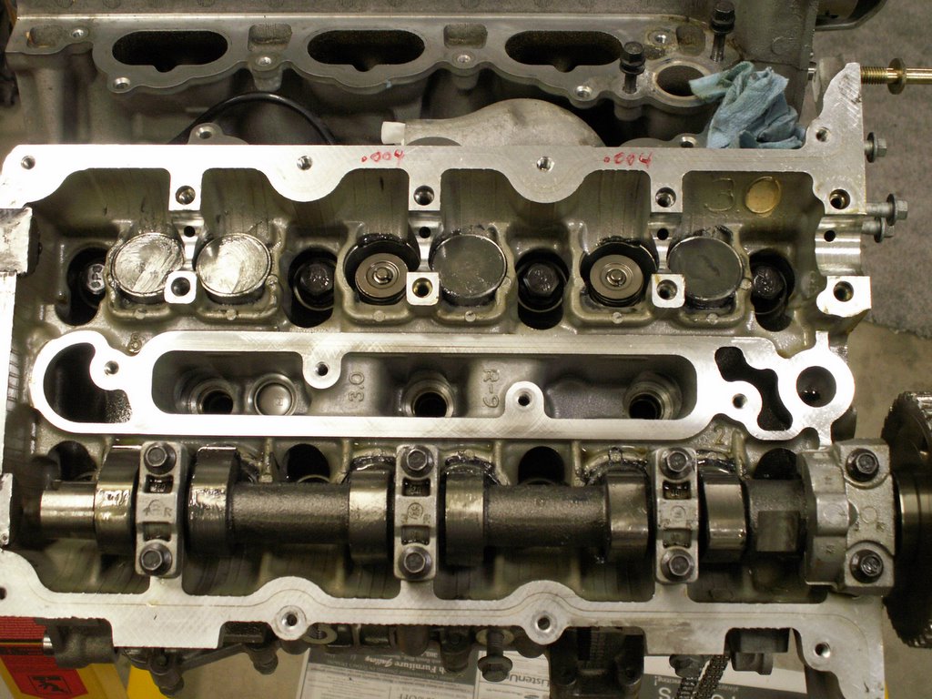 I've also removed the shims and buckets from the two "problem" intakes. These come out very easily using a shop magnet. The shim and bucket is a two piece design with very close tolerances. In mechanicla engineering this fit is called a "wroking fit" with less than .0005" clearance. I needed to heat the assembly up to 200 deg F so that the oil film underneath the shim would become viscous enough to loosen the shim. Then I needed a special pair of sof pliers and magnet to assist. I tried an air blast, but that did nothing. I'll mic (micrometer) these two shims, then purchase the next smaller shim bucket size from Jaguar. In the picture, you'll notice a lot of grease. This is engine assembly grease. I've coated every moving part of the engine as a "preliminary" lube. Assembly grease greatly assists in bearing lubrication on eventual startup. It is designed to dissolve in engine oil.
 Finally, here is a group picture that shows all of the parts removed to get to the buckets. From the left: the RH chain tensioner; the curved chain track; the two intake bucket shims; the fixed chain guide with the VVT pump; the intake cam from the RH bank. The chain was left on the crank sprocket as it can so easily be reversed.
Here are two closeup pictures of part lines that the timing cover gaskets must cross. The factory uses a small dot of silicone gasket material at these pointe to ensure seal. The factory gasket is not enough to prevent an oil leak.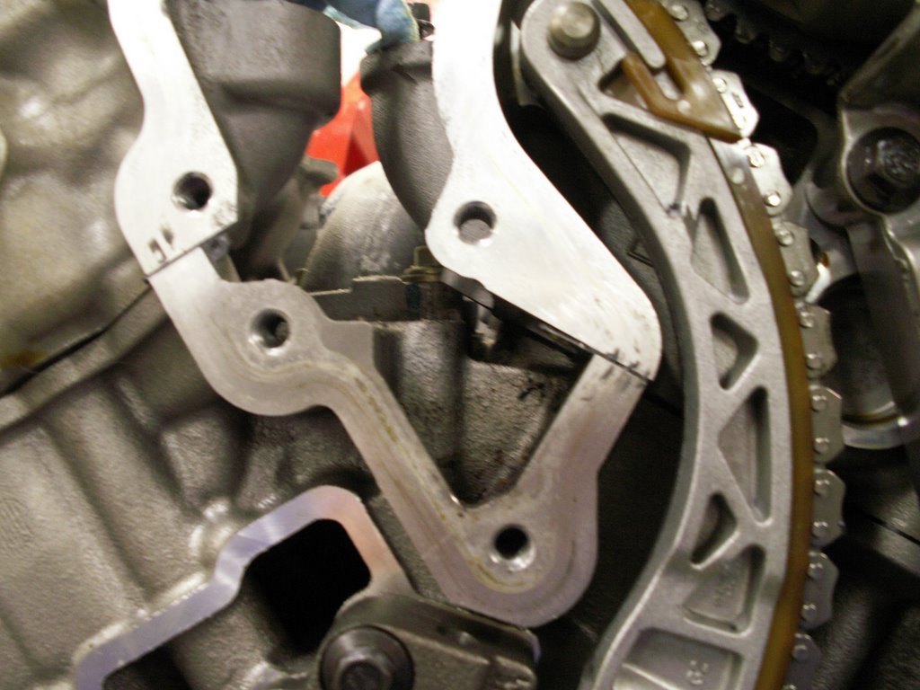
 The first pic shows the inner part lines from both heads as they mate to the engine block. The second picture shows the outer RH head to block partline. This one is perticularly difficult to clean of old silicone because of a dowel pin locater used on the timing cover. The aluminum surfaces must be cleaned and prepped for the new gaskets using a soft tool as anything hard will marr the surfaces.
Now I get to go to my local Jaguar parts department and spend LOTS of money. More to come. In a future post, I'll reassemble this so that you can have a complete process for valve shim clearance correction.
If there are any questions, comments or additional discussion wanted, please email.
Enjoy!
posted by skhannes at 3:53 AM
![]()
![]()

4 Comments:
You can do the valve shims without camshaft removal. Either get the special tool from Jaguar that depresses the valve shim bucket or just use a flat blade screwdriver to depress the valve spring bucket manually. I've done them both ways with no trouble. The valve springs are bee hive springs and are very weak during the closed valve position and are easily depressed with just a little hand pressure. The blow gun that Jaguar supplies to blow out the shim has a fan shaped attachment that blows a burst of air around most of the shim and I.ve never had a shim that wouldn't blow out. I've even managed to replace a few broken valve springs without removing the camshafts though that's a tricky one not meant for the faint of heart. One other thing I should mention while I'm leaving this message. You really shouldn't renumber the cylinders to match the Ford numbering system when you speak about the firing order or cylinder sequence. The reason being that at some point in the future when someone has a check engine light on and they get a code that says "cylinder number 5 misfire" or "cylinder number 2 coil primary fault" or "cylinder number 4 injector fault" you will want to know exactly which cylinder Jaguar is talking about. I would hate to see someone that has been following your project on the Jagtalk message board be misled into an incorrect diagnosis or worse the spending of unnecessary funds on imporperly diagnosed problems.
Real Tech:
I appreciate your input. I was waiting to hear from a Jag technician that had actually removed the shims on an X-Type as the JTIS documentation available doesn't specify a service interval or a special tool. I've heard from one other tech that he thought the V8 tool listed is one and the same tool that you're referring to.
On the cylinder numbering, I thought long and hard about how to pubilsh the error that I found in JTIS. I went out of my way in this blog to first document that the JTIS numbering and firing order does not work. It lists the firing order for the generic sequence with the cylinder numbering of the Jaguar specific. I've heard from at least one Jaguar tech that had suffered much frustration in trying to diagnose a problem because he was unaware of this error. Secondly, I specified that later documentation cleared the error in early JTIS. Finally, I make a clear and deliberate point that I am not using Jaguar numbering and firing order so that I can communicate with other non-Jag Duratec owners who also read this post and talk about the same firing order and cylinder numbering sequence since, from what I can see, Jaguar is the only mnufacturer that changed the sequence and numbering. If one reads the posts, I am confident it is clear, and in every place where I show or discuss the generic firing order I state that up front.
Thakns again for your input.
I don't think the V8 valve shim tool will work but I haven't actually tried it. If you look in the S-Type engine section of JTIS you will see the correct V6 tool with part number listed.
Jaguars JTIS is notorious for leaving out information that the average backyarder will need to make repairs. That's why I don't normally recommend it's purchase unless you intend to also get the various other discs and paper books that go along with each model. I haven't used a JTIS in months since I have access to the online technical information which is much easier to use though not necessarily faster.
Though I've been working on these cars for many years I still have to look up cylinder numbering and firing orders for everything but the X-Type every time I get a cylinder specific code. Jaguar has changed the way the number the banks and cylinders so many times on the same engines I can't keep it straight. Is it A-bank or bank 1? Then they will number the cylinders A-bank 1,2,3,4, B-bank 1,2,3,4, and give you code P0307 cylinder #7 misfire. Excuse me but which cylinder is that? That's the only reason I mention the renumbering, Jaguar makes it hard enough as it is. This is not new though as the Series I and II I believe had the cylinders numbered with number 1 at the rear of the engine.
Real Tech - On the cylinder numbering - On top of it all, the JTIS CD #21 X-Type engine description is simply wrong which is a much bigger problem even for a Jaguar tech. In it reference is made to the cylinder numbering of the V6, Jaguar specific order, then using the firing order of the Generic Ford Duratec. This is simply an impossibility. So, even for the Jaguar tech, unless you happen upon the corrected firing order and correct cylinder numbering (which was identified for me in a factory spec PDF, non-JTIS, by another tech), lots of frustration will occur. I explain that in my blog and list both Jaguar and generic firing orders with the correct cylinder numbering for each. So, my blog is actually more clear than the factory materials of rev 21 JTIS
Post a Comment
<< Home