Sunday, December 18, 2005

Motor Project # 4 - More Disassembly

From Steve Hannes - Project # 4 is meant to inform and educate. Well, the engine is finally on a stand. I did the final removal from the carrier and removed the automatic trans, which is going to a transmission rebuilder, sold to him as a core. Any final outcome of this motor project regardless of the direction will include a manual transmission. I am looking for a Jag 5 speed manual box if anyone knows where I can find one. Here are some pictures as I picked the engine trans assembly off of the carrier.

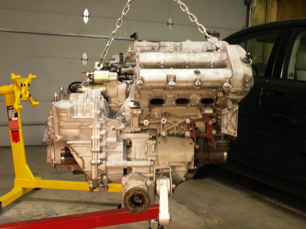
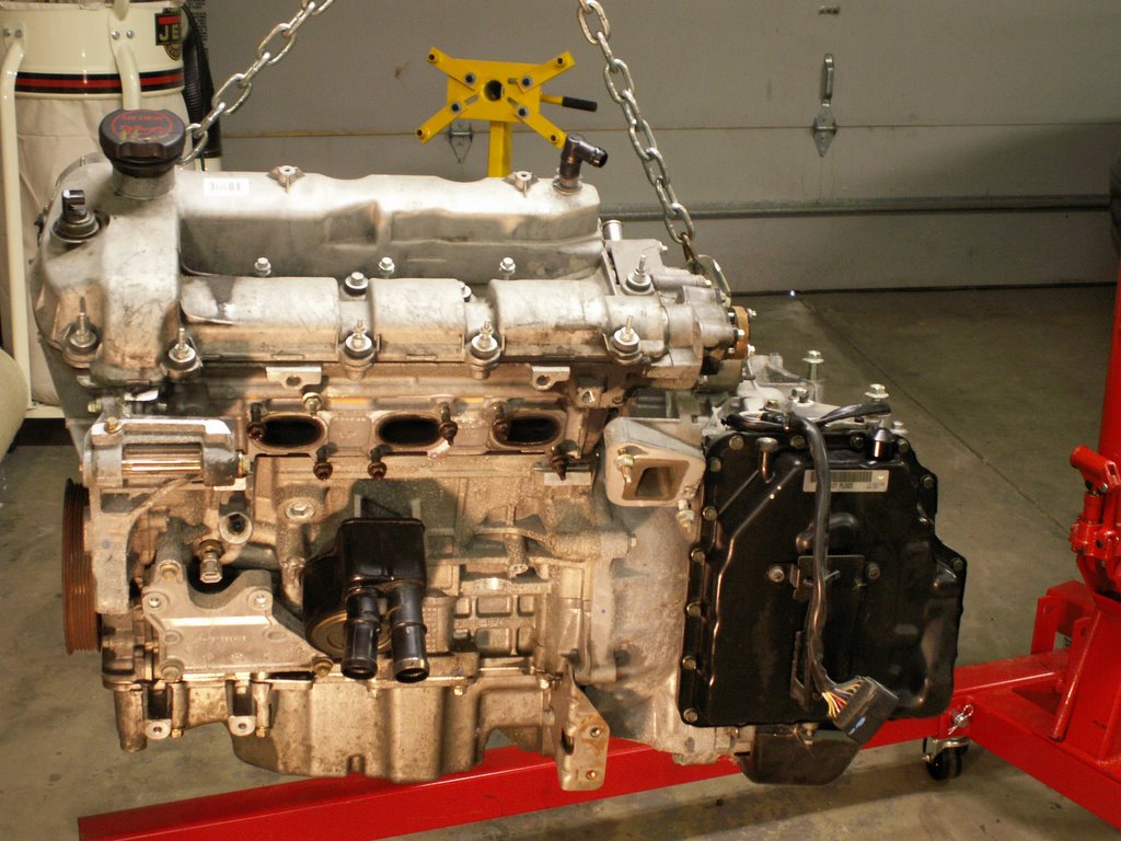
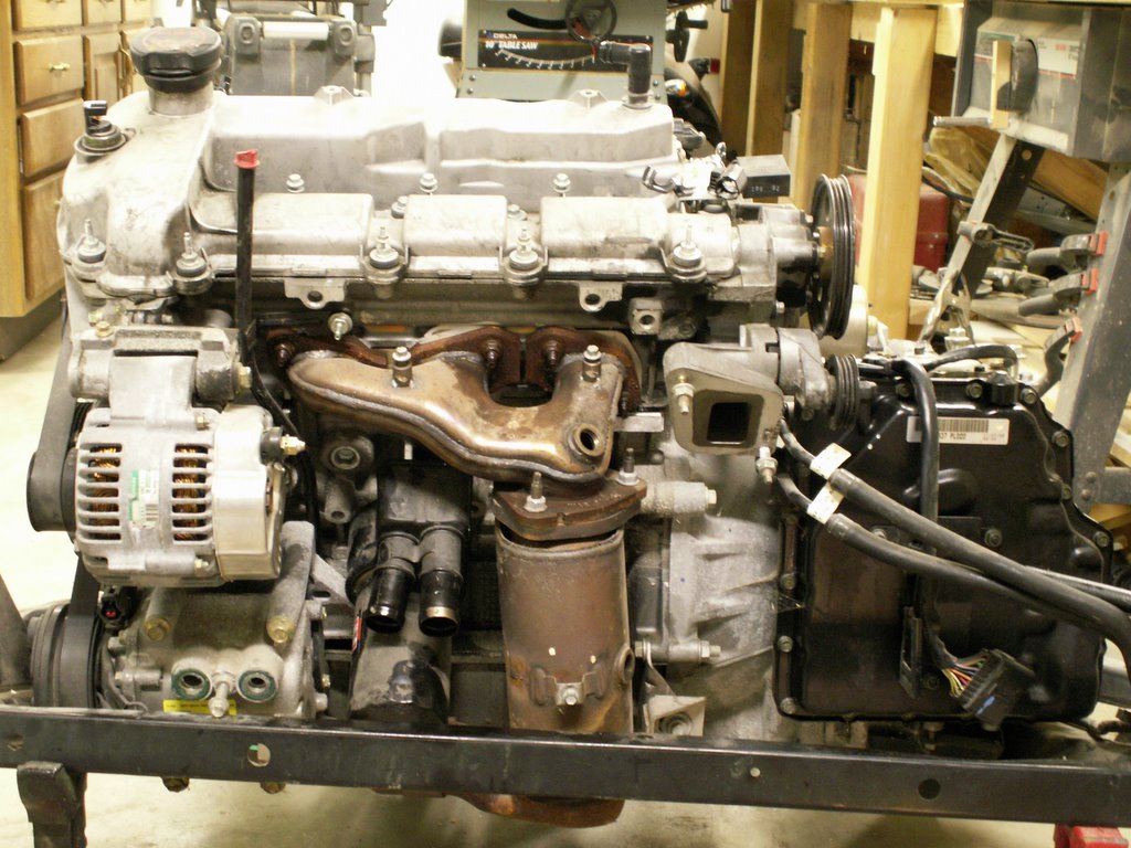
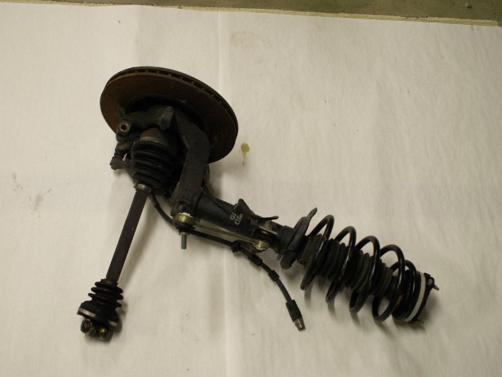
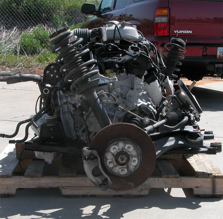
In the first picture, you can see the transfer case in place, still attached to the auto transaxle and I left the engine anti-roll mount in place, which I call the lower motor mount. The pictue on the upper center shows the front of the motor with all of the accessory hardware removed. Just the crankshaft pulley left to come off. The picture on the right shows the auto transaxle pan. 
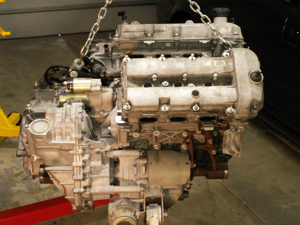
The final picture shows the engine top as best I could reach it with the camera. I've removed the fuel injection plenum and the remaining coolant hardware which is all metal tubular.

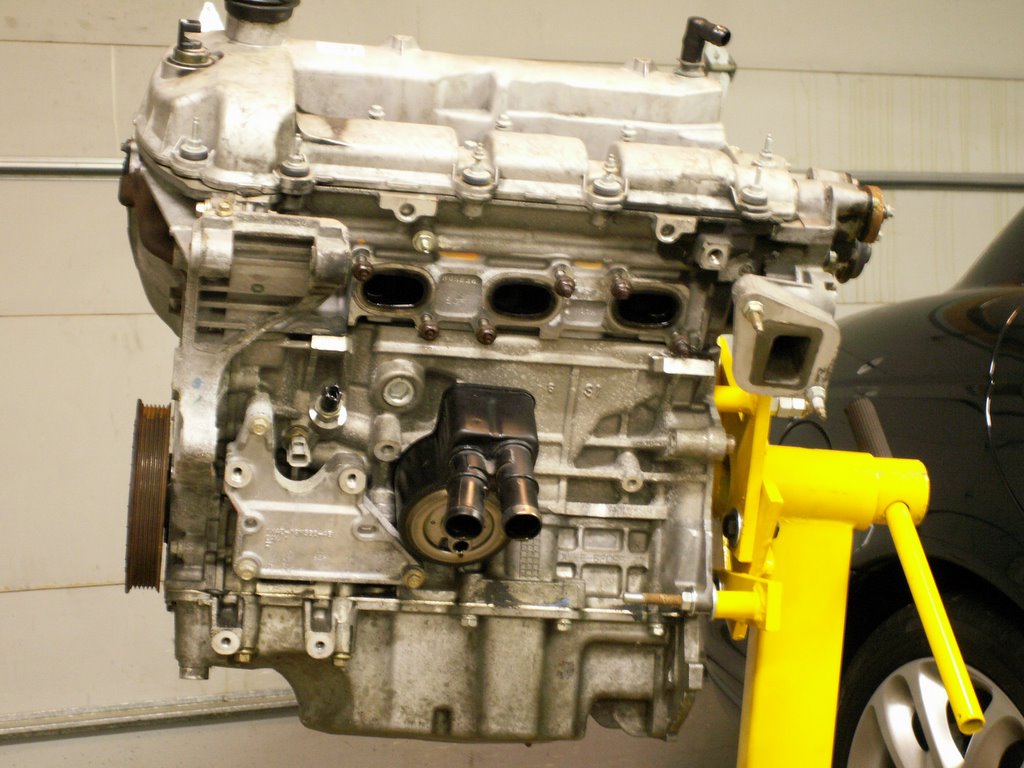
Interestingly, when I drained the transmission I found the fluid to be a very dark purple colour. Not nearly what I expected to find from a trans with only 15K miles on it. I assume that Jag uses Dexron fluid which should be much more red in colour. Another interesting factor is the design of the transfer case. It make a direct internal connection with the auto trans through a jack shaft. The only thing separating the transfer case fluid and the auto transaxle fluid is an internal seal in the transfer case. Of course, if this seal is breached, then fluids would interchange. In R/R procedures Jag uses a special tool to keep the jack shaft from coming completely out of the transfer case. The reason for that is the jack shaft uses a soft metal spring clip at the end of the spline to secure it in place in the trans axle. When it is removed, the spring clip is pretty much destroyed and would destroy the seal if the shaft were pulled through it. One future project I will completely disassemble the transfer case. Since I probably won't use it again and I'm sure I can't get parts for it, I'm curoius what it looks like inside.

BTW - I know that Jag states these cases are sealed for life and never need changing. I'm not of that school. Another point often missed is that JTIS GIVES a recommendation for an auto fluid change every 30K miles for extreme use conditions. To me, that means change the auto trans fluid every 30K miles.

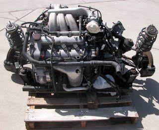
And, now - just the engine on its stand. MY BRG 2.5L Sport anxiously awaits in the background as at least one possible outcome of these projects is that she is the recipient of this 3.0L motor in whatever form it finally takes. Enjoy the pictures!

Thursday, December 15, 2005

Motor Project # 3 - Waiting to Exhale

From Steve Hannes - Project # 3 is meant to inform, educate, inspire thought and Discussion. I am continuing with the disassembly of the 3.0L Jag V6 motor project, but taking a side road. I'd like to present some forensic evidence regarding the factory design of the exhaust system on the V6 transverse layout with the hopes of sparking some expert discussions and ideas. In my personal analysis of this exhaust design, there is potential for increased performance. First some commentary - I've read some about the design of Ford's duratec platform. The important design goals were to produce a very low emissions engine throughout the temperature range from warm up to operating temperature, along with low fuel consumption. With that in mind, one elemental factor in reducing emissions is heat. Thus it is part of the functioning design of a catalytic converter to operate most efficiently when hot. Now, for the Jag X-Type design influence on the 3.0L Duratec - Waiting to Exhale: The exhaust system is an asymetrical design, in the layout, in materials and in terms of flow. Here is a picture of the exhaust manifolds, catalytic converters and collector assembled as they would look on the engine. Notice the different shapes of the manifolds, and the positional layout of the Cats.

Here are some pictures of just the manifolds and cats. The one on the right coming from the outer (or left) bank is fabricated in Stainless Steel. The manifold on the left, from the inner (or right) bank is cast iron. Purely from a heat transfer and flow perspective, this must mean there is an imbalance from one bank to the other. To a performance engine designer, this looks like a golden opportunity!

And a point about the earlier reference to heat and the efficiency of cats, the jag design has these HEAT generators tucked extremely closely to the aluminum block - good for the maximum functioning of the cats, but at what expense to engine temps and premature wear of engine and extremities, I wonder. Another impact on efficiency is the different orientations of the Cats - one horizontal, one vertical. The back (right) cat takes a severe bend coming out of the cast iron manifold, where the front bank cat flows straight from the SS manifold. To protect against some of that heat, Jaguar went to extra efforts to shield the cats using several heat absorbing covers. There is one to shield the steering rack, for example, and one to shield the power steering pump. NOW FOR THE CHALLENGE - And I am inviting any expertise in engine design, engine flow, header manufacturing, materials experts, etc. I'd like to fabricate a set of tubular headers that collect at the point of this original collector, then into one (of the) catalytic converters - OR keep the headers separate, then feed each side in to its own cat. I'll use the factory Oxy sensors someplace where the headers collect on each bank, then use the Cat monitor(s) where they belong. Now is when I'd like to be a personal friend of Jesse James on Monster Garage! I invite your design and fabrication expertise to make a set of headers materialize. In some future post with a different project # I will document the entire fabrication process.

Saturday, December 10, 2005

Motor Project # 2 - Spaghetti Anyone

Project # 2 is meant to Inform and Educate. The project is moving very rapidly right now becasue I need to get the auto transmission separated so I can sell it. After I get the engine on the stand things will slow down a lot. Since the "arrival" pics, I've stripped off all of the accessory plumbing, electrical and intake manifold. X-Type owners, want to see what your motor looks like naked? This is the front bank. Jag refers to left/right banks, but that is confusing so I'll always use the front (closest to you when standing in front of the car with the hood open). 
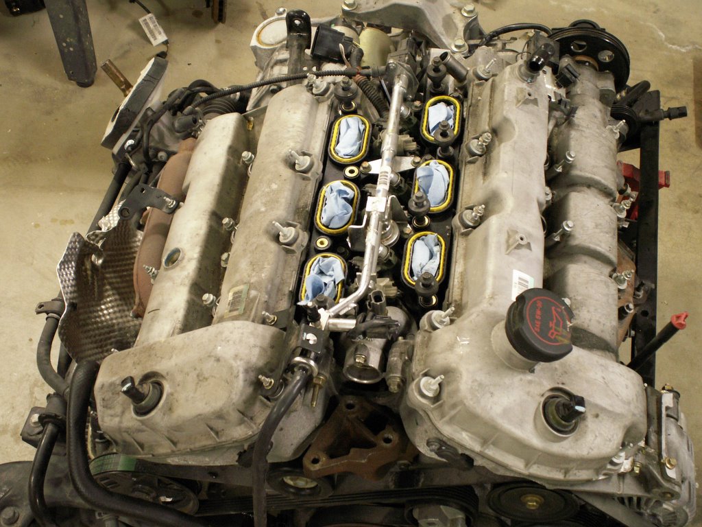
Here is the back bank. The one that lives in the dark and few ever get to see.

And a picture of the top of the engine with the intake manifold removed and all of the electrical harness and coolant plumbing. The lower intake manifold is still in place. It includes the fuel injectors and fuel rails. The yellow ovals are the O-ring gaskets that seal the upper intake to the lower.

Spaghetti Anyone?? Ever wonder what the wiring in your X-Type looks like with all of the other hardware missing? Well, here it is, laid out just about the way it sits on the engine. This one harness covers the entire engine management system. I've placed the spark plug coils where they plug in so that you can get oriented. The coil set on the right goes to the back bank, and the computer or engine control module (ECM) is plugged in too - the silver box. Every plug in the picture, with the exception of a few for the alternator and starter, go to a sensor that inputs to the ECM.

Interestingly, I found two end points that had unusual fastening. Either Jag found weaknesses in testing or wanted to ensure connection anticipating weaknesses. One terminal is the low voltage side of the starter solenoid, the othere is a ground lug found mounted to the outer left hand corner of the outer bank cylinder head. These two lugs were glued in place before the mechanical connection was made. Not quite sure what the glue was. It looked like hotmelt, but I don't believe that would stand up to the heat. Might be epoxy.

I once worked for a brilliant MIT engineer, Ken Olson. He created Digital Equipment Corp (DEC). He used to tell his engineering managers NOT to design products like they were "high school shop" projects. I've worked on Jags since my first XJ6 Series III and Ken Olson would have some criticism of Jag's coolant system. Here is a picture of about 3/4 of the plumbing! At least two coolant hoses are missing because they were cut off during salvage. I've included a few electricals that were missing from the harness photo. Jag has a bad habit of designing the cooling system with a myriad of hoses and connectors. Many of these are not even visible until other components are removed. Then, all of these hoses are form fitted, meaning they are exclusive to this model. That means they are awfully expensive as volume never gets high enough to really mass produce. And, many of us will have the unfortunate experience some day to have one of these hoses fail on the road as we tend to avoid the PM, but that's when it really gets expensive! I'm showing three of the four Oxygen sensors on the very bottom. One fell victum to the salvage process.

I know that some like doing their own simple tune ups - spark plugs, air cleaner, etc. On the X-Type, that means removing the intake manifold to get to the plugs in the back bank. If there is enough interest, I'll write a simple "practical" process for changing spark plugs now that I know where the "hidden mounting hardware" is on the intake manifold. Here is a picture of the "dark side" of the intake manifold, where four hidden screws reside. If there is interest, I'll post it as a separate project # with pics of the intake manifold from all angles.

Finally, a bonus picture - one of the strut and axle half assemblies:

By the time I post again you'll see the engine on the stand with the auto trans (long) gone.

Motor Project #1 - Arrival of the Beast

Project # 1 is meant to Entertain and Inform Here is my first report.My 3.0L X-Type motor arrived in Denver for local pick up today. Couldn't havebeen worse conditions. It was -12 deg at my house and a high of 4 deg in Denver.I needed a dock high truck to pick up from the shipper's terminal. That meantthe largest 24 ft Budget diesel truck that is available. Then 65 miles to myhouse, then return the truck - all ICY windy roads from 5000 ft to 9000 ft. This is much more than just the 3.0L motor. They shipped the entire sub-frame,engine, trans, struts, steering rack, even the front disc brakes, the ECM andthe security module. All weighed 1,012 lbs. And, as it happened, since this wasa weekday, workday, I found myself alone once I left the dock help. The drive was white knuckled to say the least. Took me almost two hours, then I had tonegotiate my 400 ft rising driveway.Once home I began building a dolly system so that I could lower the motor downthe ramp. Got that done, then realized the truck ramp had a 1,000 lb max weightlimit. This forced me to begin disassembling - removing weight to lighten upsome, also to help me better negotiate the ramp.So, my first REAL mechanical "hands-on" experience comes from removal of bothstruts (and front discs and brake assemblies), and axle half shafts. I had toremove the lower ball joints, steering rack tie-rods, stabilizers, then the halfshafts from the transfer case. This was remarkably easy and it has given me theconfidence that I've wanted as I know I'll do my own clutch someday in my manualsport. Incidentally, I've already built one of Jag's "Special Tools" used forclutch replacement - the very cool small A-Frame that supports the engine wieghtfrom up top. I've commented in the past about JTIS and how poorly it is written.Trying to follow the steps for a clutch replacement, for example, simply byreference to the CD is daunting. Now I have a real life sample to fill in theblanks that the CD doesn't provide. And, now that I know what's involved inremoving the half shafts, I am a significant way towards a lot of repairs. NEXT STEPS: I need to start separating out the parts that I'll keep and sell offparts that, regardless of the directions I take, I won't need. First thing to go will be the automatic transmission. Watch for it soon on Ebay! As this motor was so complete, I might also part out Air con compressor, Alt, etc, etc. Then, Ineed to get the motor up on an engine dolly. One that is versatile enough to let me beginexploring. More to come.