Saturday, February 18, 2006

Motor Project # 12 - Deep Breathing Exercise!

This project is provided by KARL WOLF and is meant to educate.
CAUTION: This project is NOT for the beginner mechanic and should only be attempted if you are confident in your mechanical abilities and fabrication skills, and you understand the functions of the intake side of the OBD II engine management system.
Karl continues with some performance modifications to the stock air filter box. Here's Karl: This modification is designed to eliminate the airflow restrictions in the standard airbox. This project can be combined with the spark plug change, the intake manifold porting, and throttle body cleaning (projects 5, 10, and 11) to make for a complete afternoon intake tune-up. In almost all current engine designs, the throttle body should be the real engine airflow limiter. My modifications of the airbox and intake allow the throttle body, not the airbox to be the limiting factor in the air intake system. The airbox on the Jaguar X-Type is limited by packaging and noise devices designed into the air intake system. I have reduced how these designs impact airflow. The main modification is in the top of the airbox. To disassemble the top air box half, first remove the factory inlet hose clamp. The standard clamp can be easily removed with a pair of pliers and a small flathead screwdriver. Squeeze the two large tabs together gently and pry the upper band end from the lower band end. If you are careful, you will not damage the clamp and it can be re-used. Carefully remove the MAF sensor (two screws) and set aside. Unscrew the top and look at it from the inside. 
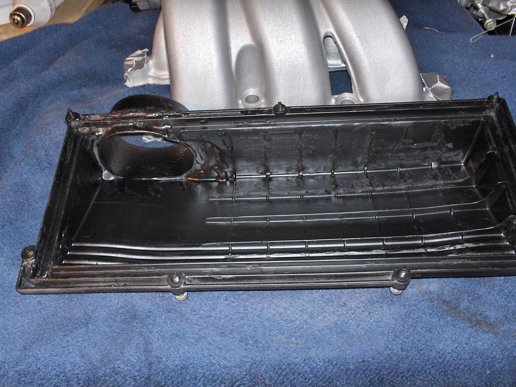
Let's start by looking at two pictures of the top air inlet box disassembled:
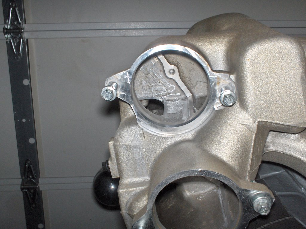
Focus your attention on the baffle plate seen in these two pictures. It protrudes into the path of the inlet tube. You can see the base of this plate at the bottom right hand corner of the inside of the air box. I removed all the lateral raised plastic from the inside of the top with a dremel, but a file or sharp blade could be used. This baffle is designed to break up the airflow to reduce noise. The reduced airflow, of course, restricts performance. The major restriction is where the airbox meets the 3" output tube. As you can see in the first picture, the lower portion is totally obstructed. You now have two options to modify the top cover: Option One (simple solution): CAREFULLY remove as much of this restriction as possible with a file, dremel, etc. This is the real bottleneck in the airflow. Take your time so you do not cut through to the outside of the box. Don't be too concerned about the area near the inside lip of the box because the filter gasket will seal this area. This is the easiest modification and my original solution.
If you stop at this point, you've made a big improvement in air flow to the TB, but this still leaves almost 1/5th of the airflow blocked. See this picture with the baffle completely removed. For even greater air flow: Option Two (more serious modification): Remove (cut) the 3" tube which houses the MAF sensor as close as possible to the airbox top. Purchase a 3" aluminum or thin gauge steel tube. You only need about 3." I used a piece from an old intake. Make an oval out of the tube and set it inside the airbox top. Make sure that it covers the original opening completely. Trace around the tube and then cut inside the lines. Use a dremel or drill a number of holes and "connect the dots." Finish by trimming until you get a tight fit.
Sand all the edges and rough up the surfaces. Make sure you have at least 1" available on the outside to clamp the new connector tube. You will have to trim this to fit later. I used two self-tapping screws to hold it in position and cut off the protruding tips. Use flexible two-part epoxy to seal the tube to the airbox lid. Clean all the surfaces completely. Finish off with a quality vinyl paint on the outside and Armorall or silicone spray (well wiped off) on the inside. Trim the inside of the MAF tube so that air will flow smoothly into the tube. Connect the MAF tube to the metal airbox tube with a silicone 3" connector and hose clamps.
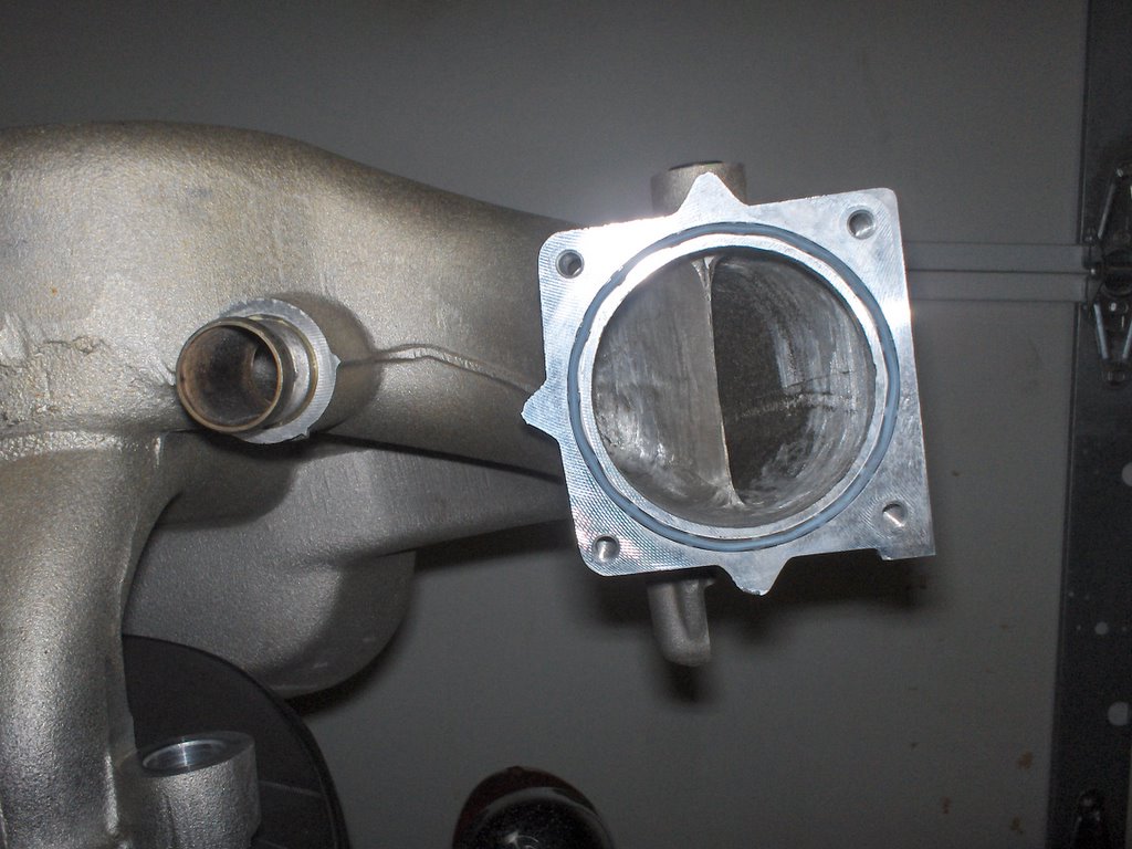
Next, I modify the cold air intake (lower portion of the airbox) by adding an additional cold air pickup next to the two existing cold air inlets. Continue disassembly by removing the lower airbox and use a holesaw to drill an additional 2" hole. Purchase the 2" flexible tubing at any auto parts store. It is sold as heater or intake tubing. The flexible 2" duct routes over the top of the radiator and next to the stock intake tubes. This will allow more airflow into the lower part of the airbox. 
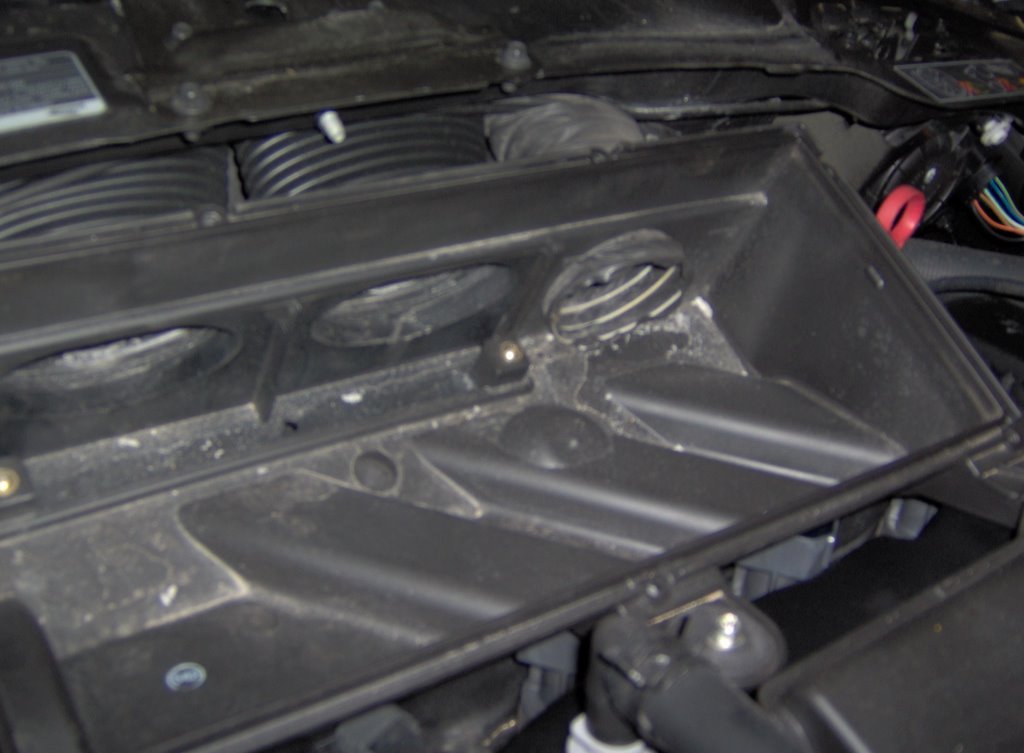
A picture of the lower portion of the airbox is shown here in place with the new air inlet modification. See the third air inlet to the far right of the box, next to the two original oval inlets.
Here is a picture of the grill. Although a little difficult to see, the additional cold air inlet is just barely visible to the left side of the original left air inlet. Here is a picture of the air box reassembled after all of the modifications. Very little has changed in appearance from the stock air box. I use a K&N filter, but you can use a stock filter. Just make sure to replace it regularly.

Cost? About $15.00 in parts. Time? One hour for the simple solution. Two to three hours for the more complex solution. The great thing about these mods is that unless you know what you are looking at, the air intake looks totally stock and really does not change anything but allows more airflow. You may notice a very small increase in intake growl but it is only due to the increase in airflow, not the growl associated with an aftermarket air intake. These aftermarket intakes take air from under the hood. Some of the benefits of these kits are negated by the additional heated underhood air.

Notice to all blog readers: We're looking for more projects that will help you improve performance of your Jaguar X-Type. What would you like to see next? Here's an incentive: Anyone want to see the actual HP increase for this project via Vericom results? Just use the "post comments" on this blog with a request for another project you would like to see and your email address! We'll email the results to you as a thank you! Coming soon: We're hot on the trail with some exhaust modifications. You might remember in project #3, we examined the stock exhaust layout used on the X-Type. It offers a bounty of performance opportunities and we're taking advantage of all of them. See it in an upcoming project post.

Sunday, February 12, 2006

Motor Project # 11 - Clearing Your Throat!

This project is provided by Karl Wolf and is meant to educate. This project can be accomplished by someone with average to high mechanical skills - not for beginners. CAUTION: Give careful consideration to this maintenance process as Jaguar is so concerned improper cleaning of the throttle body will occur, the factory will deny warranty to the TB even if they find evidence it has been cleaned. It is advisable to wait until after warrany has expired. Karl continues with some simple/easy maintenance items while the intake manifold is removed. Karl describes a safe way to clean carbon build up on the back of the throttle body. Jaguar uses a clearcoat on the inner surfaces and cleaned improperly or left uncleaned, air flow as well as throttle blade functions can be adversely impacted. This can be combined with project #s 5 & 10 and called an intake tuneup. Once again, here's Karl: Throttle Body Cleaning As Steve has indicated, the Throttle Body is a relatively delicate part. Standard carburetor cleaners should NOT be used under any circumstance! That being said, there is a safe way to clean the TB. Before we get to that, let's recall where the throttle body might be at the moment. If you've been following projects in this blog and are using the instructions to remove the intake manifold to change spark plugs (project # 5), then you recall the throttle body was disconnected from the intake manifold, but left to "float" in place as a shortcut so that electrical and coolant connections could be preserved. It is possible to follow these steps without removing the throttle body as it was left in project #5, however, you will be at a slight disadvantage over these pictures because the opening needing cleaning points toward the windshield. If you decide to remove the TB completely, it is water cooled and has inlet and outlet rubber hose connections that lead to the engine coolant system. Be very careful as these hoses are formed and short in length. As they get old, they become brittle. If you see any signs of this it is advised that you replace them. As a rule of thumb, if you have over 50K on the clock, or any 50K increment, replace them. It'll save you a breakdown on the road. BTW, make sure the engine is cooled down (cold) before you disconnect these hoses. They will leak coolant even if you remove some of the coolant from the system, which is advised. They reside "high" in the coolant system so you don't need to remove all of the coolant. You also have two electrical connections to remove too if you choose to remove the TB - the Throttle position sensor (TPS) and the throttle motor connector. TPS and motor are the "throttle by wire" system that is used on the 2.5, 3.0L V6 in the X-Type. PS - The diesel versions (not in the US) still use a throttle linkage. Picture 1 - Front of Throttle body (click on any picture to enlarge) This picture shows the front of a throttle body after about 15,000miles. It doesn't look bad but you can see slight darkening around the throttle blade. This is the view you would see when you remove the rubber air tube coming from the air filter. Picture 2 - Back of Throttle Body (to the intake manifold) This picture demonstrates that what you don't see can hurt drivability and performance. This carbon/oil buildup is not unique to the X Type. All throttle bodies will develop crud buildup over time. This buildup comes from the oil and fuel byproducts recirculated within the motor. The difference in the X is that it is drive by wire. As mentioned above, this means that the only connection between the gas pedal and the TB is an electrical wire. No cable activates the throttle blade. There is also no separate idle air valve. The idle is controlled by the TB butterfly. This means that air is always flowing through the butterfly so it does not have some of the self-cleaning of a conventional cable operated TB. When the butterfly closes fully, it scrapes some of the crud away. With the conventional TB, when the butterfly sticks we just press harder on the accelerator to free it. Again, Steve has listed the partial removal of the throttle body in another post. It can be cleaned without being totally removed. Safe solvents are available to clean it. The X uses a coated throttle body. This is a coating designed to reduce buildup. You MUST use a product that specifically states it is safe to use on coated throttle bodies!! You will also need a soft detail brush or your old toothbrush. (Please throw it away after use in this project!) Picture 3 - Throttle body after cleaning. This picture shows the clean throttle body along with two products safe to use. Use them carefully, making sure you keep the TB in the mounted position. You do not want to hold it sideways as the solvent may run down the butterfly shafts and damage either the throttle motor or the throttle position sensor. Use the solvents per their instructions and the brush to remove stubborn deposits. As a side note: Many X-Type owners have switched to K&N air filters. Anyone concerned about using a K&N filter should view these pictures. You should be more concerned about the junk buildup from inside your motor than the minute particulate difference between a stock and K&N filter. And yes, changing your oil regularly with a high quality oil will also reduce this buildup. Hope you find this project useful. Enjoy!

Thursday, February 09, 2006

Motor Project # 10 - Just Breathe!

This project is provided by KARL WOLF and is meant to educate. This project can be accomplished by someone with average to high mechanical skills - not for beginners. Karl is an expert in many areas of modern automotive technologies. He has years of experience with intake/exhaust efficiency and port/head flow dynamics. He provides some simple, low cost techniques to improve intake flow dynamics on the X-Type intake manifold. These techniques will work on the 2.5L and the 3.0L V6 Duratecs produced by Jaguar. Here's Karl: The X Type motor is a very well designed, very efficient motor. As Steve has pointed out, the major areas that can be improved upon are the intake and exhaust systems. This procedure could easily be done when the manifold is off during a spark plug change. This post will describe how to gain improvements in airflow thru the intake manifold. I will point out areas of concern and how to eliminate them. Keep in mind that the manifold in these pictures has less than 15k on it. Carbon builds up very quickly behind the throttle body which can hinder airflow. In another post I will detail how to SAFELY clean a coated throttle body. Jaguar coats these throttle bodies with a clearcoat to maximize air flow, but this surface is easily damaged or destroyed if you aren't aware. Remember that the Jaguar intake design consists of two different intake tracks. These intake tracks can be switched back and forth through solenoid control valves and are selected (opened/closed) by the ECM under various RPM, load and engine temperature conditions to maiximze air flow and ultimately maximize engine torque. The FIRST area for improvement. Picture 1, the area directly behind the throttle body(click on any picture to enlarge it): As you can see through the throttle body port, there is a large (vertical) flat surface which separates the two runners. This area is directly behind the Throttle Body and is the first bottleneck. This area needs to be smoothed and brought to a point to allow a smooth transition from the TB to the two runners. The front angle should be biased/angled so that the left runner is more exposed. It has a shorter radius and inherently greater restriction. Picture 2, improved port: Smooth this area with a Dremel, drill, or die grinder and take out any internal lumps and casting slag. It needs to be relatively smooth but doesn’t have to be perfect. Refer to picture 1 and you will see that the area quickly becomes covered with carbon/oil residue. The oil residue comes from reminants of the PCV which utilizes the intake manifold as a crankcase breather. The SECOND area for improvement. Picture 3, the intake runners: In this picture the lower intake manifold (black plastic) is assembled to the upper manifold the way the engine would receive the assemblies, except it is turned upside down so that you can clearly see down the six oval ports as they flow to the intake valves. Note the six green fuel injectors in place. As you can see, the aluminum intake runners are smaller than the oval ports in the black plastic lower intake manifold. This causes a restriction in the airflow capability of each cylinder. Attach the plastic lower manifold to the upper as shown here. Scribe a line around the inside of the plastic ports on ALL areas showing from the aluminum upper manifold. Separate the two manifolds and carefully remove the material from the aluminum ports until you come to the scribe marks. (NOTE: if you do not want to remove the lower manifold, acceptable results can be obtained by creating a template of the lower manifold ports. Use a thin piece of cardboard and carefully press it onto the lower ports one side at a time. Make sure you have the mounting points as a reference. Carefully cut out the ports on the pattern and transfer them to the upper manifold.) Work carefully and smooth the port transition into the manifold runner. The 80 grit sanding cylinders work best as they do not load up with the aluminum. Picture 4, Improved ports: You should be able to match the ports exactly to the lower manifold. Look through each oval, compare to the picture above and note the aluminum landings are now gone and these upper intake ports now match the lower (black plastic) ports. The THIRD area for improvement. Picture 5, the manifold valves: This area requires the least work. Look for any casting areas where there is not a smooth transition from one area to another. I found a large area in the lower surface of the upper port. I also smoothed the left edge of the machined surfaces to enhance flow. Picture 6, Improved port: Thoroughly clean the inside of the manifold to remove all the aluminum filings. I first used air to blow out everything possible. I found that a large plastic storage bin filled with water and car wash detergent works great. Just make sure you remove the MAP sensor from the manifold before cleaning. Conclusion: How much additional power can you expect? The middle of winter in Chicago is not the best time to test this out. Experience tells me that these modifications should net about 10HP along with increased mileage. Cost? About $10 in supplies and 2 hours time. Watch for future projects that test the manifold modifications. We'll look at the "other" end of the process too - the Exhaust end. Enjoy.

Sunday, February 05, 2006

Motor Project # 9 - Calipers

From Steve Hannes - This project is meant to entertain. This is a very short post and quite off track from the theme of my blog. In acquiring the entire front sub-assembly of the 3.0L Jaguar engine and transmission, along with it came bunches of extras like the entire front suspension and brakes. As a sideline, and to keep myself entertained while the engine project is idling, I've rebuilt the front brake caliper assemblies. These will go on my British Racing Green Sport the next front brake job. Click on picture to enlarge.