From Steve Hannes - This project is meant to educate.
Click on any picture to enlarge
It's been a while since we last visited the 3.0L. We left it with a valve clearance issue. Two intake valves on the right bank, one from the #1 cylinder and one from the # 2 cylinder (Generic Duratec numbering and timing), were out of tolerance by .oo4". In this post I'll take you through the process to replace these shims, install the intake cam and retime the right bank.
For the shim replacement I've followed the JTIS to the letter, which specifies cam removal to change valve shims. If you've followed my posts, you're aware of the WORK involved in doing that (and the cost! About$400 in gaskets and parts for a DIY!). In the reverse process I will get all of this stuff back together, then at the end of the post I'll show you a shortcut to remove/replace shims that requires no removal of the cam, which requires no removal of the timing cover, which requires no removal of the timing chain, and yes, no special tools. The shortcut was actually suggested by one of the Jaguar techs who reads this blog. I've tried it and it works, but you need to be EXTREMELY careful not to damage the shim buckets. Additionally, he uses a fan blowgun attachment to remove the shim from the bucket. Instead I use a strong magnet as I don't want engine oil blown clear across my garage and everywhere in between.
Well, lets get our hands dirty.
With the intake cam removed from the right bank (pictures in previous project), I've replaced the two out of tolerance shims with the correct ones. It's simple to calculate the correct shim size. From the original clearance measurement (.004") I need to reach a factory spec of .008" to .009", so:
.008" - .004" = .004" (smaller shim than the existing one to correct clearance)
When I removed the first shim it measured 0.1005"
.1005" - .004"= .0965"
For this first shim, I need to replace the .1005" shim with one .0965. Jaguar sells these in several mm increments. .0965 = approx. 2.45 mm, I purchased the closest size 2.42 mm which is .0952". This will give a clearance of closer to .oo9", still in tolerance and, keep in mind from my previous post, these gaps tend to decrease as valves seat, although I should be fully seated on this 15K miles engine.
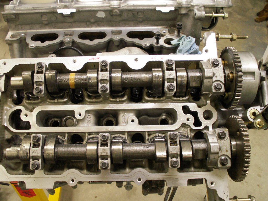
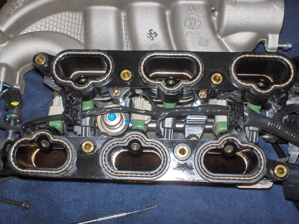
The shim replacement is now completed for both out of tolerance valves, time to reinstall the intake cam. I will not go into all of the details, but mention some important steps. Look at this picture of the right bank intake cam and count from the left, you'll see three bearing caps (two bolts each) and a fourth larger cap to the right, that controls lateral play.

- Remember that each cap MUST go back in the same place and same orientation.
- The caps have locating dowels on each bolt hole so they're not going to seat completely flat from the start.
- Generously lubricate the entire cam and bearing journals with assembly grease, place the cam in position, lubricate the caps and the shims.
- Be very careful with the fourth (larger) cap. It has a diagonal oil passage that is drilled from the bearing surface to the lateral face bearing surface. Do NOT pack this with assembly grease as it will take too long on engine startup for the grease to dissolve. Make certain this passage is clear!
- This is a General note. I'll make it once as I will probably forget somewhere in the future. I use anti-seize lubricant on ANY steel bolt being threaded into aluminum! All of the cam cap bolts are steel and the head is aluminum.
- The key to correct cam assembly is: start all bolts and thread down evenly! Once the cap dowels begin to make contact in the head, I only turn each bolt 1/2 turn starting on the far right (fourth cap), inside/outside bolt, then move to the next cap, 1/2 turn inside/outside bolt, and so on. Return to the right side and repeat another 1/2 turn on all bolts until all caps are seated but hardly tightened.
- Now you are ready for the torque wrench. The torque sequence on these cam caps is the same we've been using to run the bolts down. Start at the large cap - inside/outside bolts, the move to the next cap, repeat, capish? JTIS torque spec is: 10 nm. Don't (ever) retorque. Click once, go on to the next bolt, capish?
Now let's time! To retime the right bank there is the easy way or the Jaguar JTIS way. I'm going to show you the easy way because if you try to read and follow JTIS, it'll make you crazy, your hair will fall out, your fingernails will grow to 12 inches long and we'll have to visit you in a special place and wipe the oatmeal off your chin...I'm sure you don't want that!
All of the JTIS assembly stuff (Engine - 303-01; steps 28 through 31) are pretty much malarchy! The clock settings are mostly meant to put the intake/exhaust cams (one bank at a time) in the most relaxed positions. The actual timing of the intake/exhaust cams to the crankshaft is never really spelled out and there is a significant chance the engine will not be timed correctly following these rote instructions. Never is the intuitive instruction given here.
Principles of Timing a Duratec: If you forget everything I've ever said, just DON'T forget this:
For the right bank: 23 chain links from the crank keyway to the exhaust cam timing mark, another 15 links to the intake timing mark.
For the left bank: 23 chain links from the crank keyway to the INTAKE cam timing mark, another 15 links to the exhaust timing mark(intake/exhaust cams reversed left/right banks). It's just that simple!
With this information you can practically put a blindfold on and time this engine with tactile skills, perfectly every time. Here are some subordinate rules:
- For timing, remember that the one and only common and FIXED position is the Keyway on the crankshaft. Everything gets positioned from this point.
- ALL link counting (either bank) and ANY rotation of anything is CLOCKWISE.
- Put anti-seize compound on any steel bolt threaded into aluminum.
- Put a liberal coating of assembly lube on all parts - chain, guides, etc.
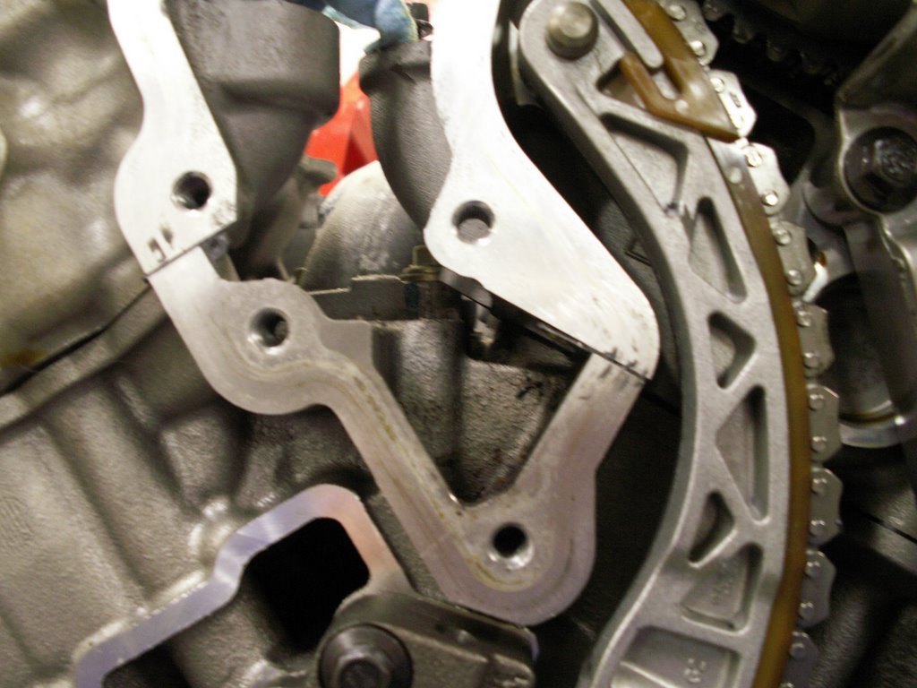
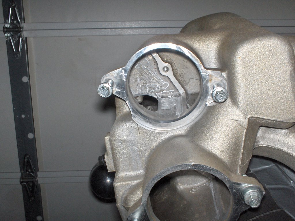
First step, assemble the stationary chain guide. It is the one piece cast aluminum frame containing the intake VVT pump solenoid. It has three bolts, one of which gets tightened first. Also, don't forget the small dime sized o-ring between the pump and the oil passage that feeds the the VVT. Here is a picture. 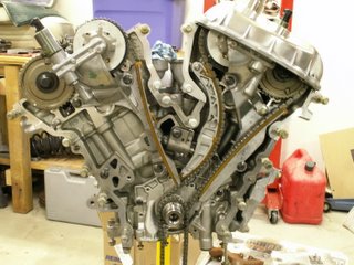 The bolt that gets tightened and torqued first is the one directly under the exhaust cam sprocket. However, you still want to hand tighten all three, the other two are top/bottom of the chain guide. The reason you're torquing the bolt under the cam sprocket first is because it seats the o-ring with the VVT oil passage. JTIS torque spec is: 25 nm.
Now you're ready to place the chain on the sprockets. The relative ideal position for the right bank timing is: crankshaft keyway 7 o'clock (make that pm not am...nah, only kidding about the pm), exhaust mark at 8 o'clock pm...nah still kidding, and intake mark at 1 o'clock. This is just where we positioned everything to disassemble.
Place the chain (so it will rotate in the same direction it was removed) over the intake/exhaust sprockets. Start with the mark on the exhaust cam and count 15 links to the intake cam. This now puts the two cams in time with each other. 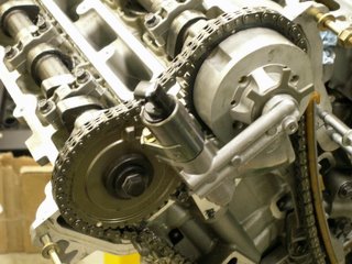
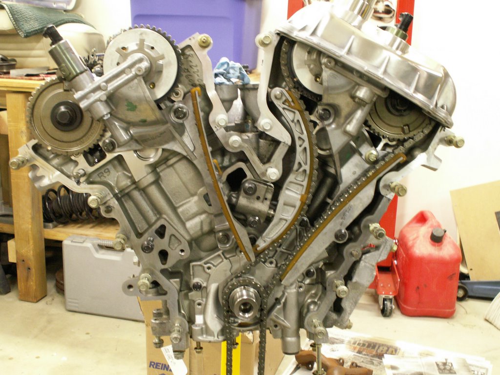
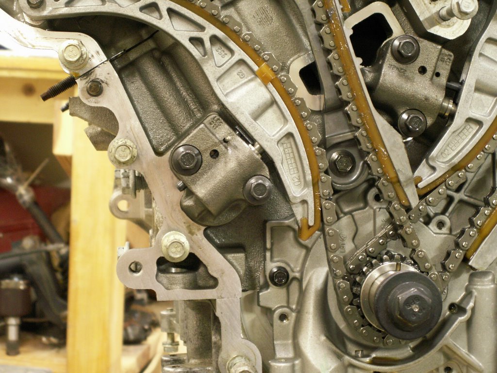
If you look closely at this picture, click to enlarge, you'll see the white dot mark on the exhaust cam sprocket, and the white dot mark on the intake cam sprocket is smaller, almost straight up at 12 o'clock. You can count the 15 links in the picture.
Now continue to thread the chain CLOCKWISE over the stationary chain guide and engage with the crankshaft sprocket for the right bank. Remember, you need 23 links from the keyway to the exhaust timing dot. The chain will seem very large and you'll have plenty of room to move it because the adjustable chain guide is not installed at this point. 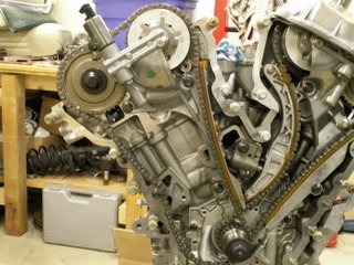
See this picture to view the chain and timing to this point. Before the adjustable guide is assembled, the link count and the slack must be taken up all in one direction - what direction? This is a test. CLOCKWISE from the exhaust timing dot all the way around to the crank keyway. If there is too much slack on the stationary guide then turn the crank slightly CLOCKWISE (See how easy this is). If there is not enough slack to make the 23 tooth count, then rock the intake/exhaust cams together back forth until you can make this count.
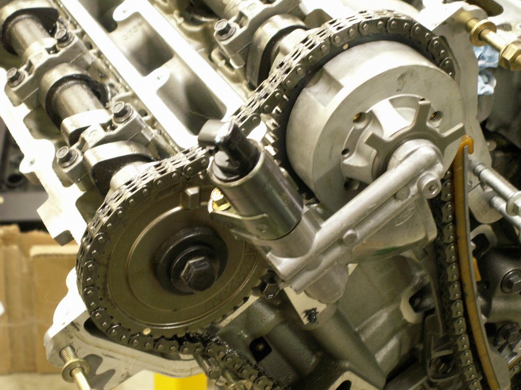
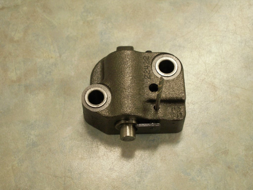
Now this will sit for a moment so we can prepare the tensioner. The tensioner is a LOAD/LOCK design. It has a sprung piston that puts tension on the adjustable guide and a secondary ratchet locked stop to keep the chain from gaining slack under load. To load the tensioner, fully collapse the piston in a bench vise, then the fixed ratchet stop must be released and placed down at the shoulder of the piston. With this, a slot in the ratchet stop will appear through an inspection hole in the body of the tensioner. Place a paper clip, or drill rod in the inspection hole and this will hold the piston and ratchet in the fully collapsed position. Here is a picture of the tensioner loaded and locked. I used a small drill bit as my paper clip. 
Now the tensioner along with the adjustable chain guide can be assembled. The guide just rides on a dowel pin and, without the tensioner in place, has plenty of freeplay for assembly. At this point you can push on the guide until it bears pressure on the chain and you'll see the right bank timing really coming to life now. As you hold it against the chain, now is a good time to recheck the link timing. Start at the crank keyway and count (how many links)? to the exhaust sprocket dot. Continue counting (in what direction)? and (how many links)? to the intake white dot. If everything is what you now know it should be, then you're ready to install the tensioner. Use the two bolts coated with anti-seize, thread them in by hand. There should be some play for the guide as the piston is still fully collapsed. Tighten the two bolts to (JTIS) 25 nm. Before you release the drill bit (to release the piston), there is a recess in the guide where the piston rides. There is enough play in the guide that it is possible for the piston to sit outside this recess. Once that is in place, release the drill bit. The piston will exert the correct amount of pressure to the guide at this time. Finally move the secondary ratchet stop in place under the guide recess and Voila!...Timed! 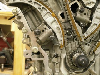
Here is a picture of the tensioner in place, torqued, just before the drill bit is released.
One final step: Rotate the crankshaft two complete turns (what direction)? to approximately the same place 7 o'clock pm (get you with that every time don't I), and recount 23, 15, to make sure you're timed correctly.
Well, that's quite the round about way (and the JTIS way) to do a valve adjustment on the V6. All together several hours of labor (Jaguar book says 5/6 hours' labor) and, again, about $400 retail in parts which includes just two shims.
How about a shortcut. One that only involves removing the valve covers then removing replacing the shims directly under the cams without removing them. Most manufacturers make a tool for this. It holds the bucket down so the shim can be removed when the cam lobe is opposite the shim. Talking to a few technicians, there is a tool like this for the V8, some talk about a tool, maybe, for the S-Type...Long story short, no one really knows and JTIS doesn't for sure.
With the cam lobe opposite the shim, reach back behind the cam with a flat blade screw driver, taped with black electrical tape. You need to catch the very edge of the bucket (it's a delicate operation). Force the bucket down in its recess, use a strong industrial magnet to catch the shim, it can be dislodged and removed. With the shim out you can release the screwdriver and no contact with the cam is made. Select the correct shim. Once again, place the screw driver on the edge of the bucket, depress (doesn't take a lot of pressure), slip the new shim in. Make sure it's seated in the bucket, release the screw driver...Voila!
Here is a picture with the screw driver in place and the new shim ready to go in. 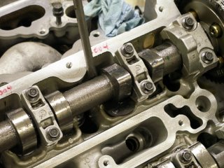
Why should you care about this project? I'm not expecting most to do their own valve adjustments, and I start with the belief that all shops are honest, but in case one is not, there is a WHOLE BUNCH of money to be made on a valve adjustment. If the shop wants to quote JTIS procedure on an X-Type, they will probably include 6 to 8 hours of labor, or more, and anywhere from $400 to $600 in parts. Then they can perform this shortcut and cut the labor down to one and a half or two hours. That's why you want to know this, even if you never DIY!
At this time I am proceeding to seal the engine back up. Next, I'll reinstall the lower end stuff removed in earlier posts. pan baffles, oil sump pick up, oil pan. I'm fairly convinced there isn't much I can do with the innards of the Duratec, even crossing over to the generic side. At least for the moment.
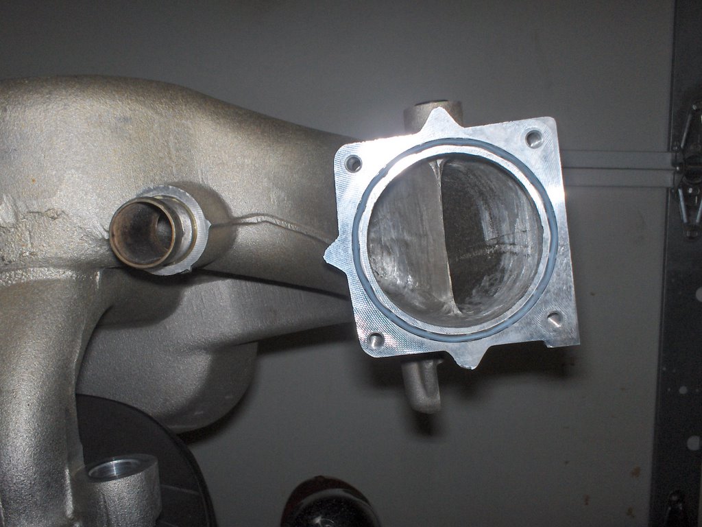
On the other hand, there is plenty to do outside, with intake and exhaust. I have been very busy pursuing two options for more efficient exhaust. One is a moderate design using other Duratec parts and a cat back layout. The other involves a full blown header set with cat back also. I will be previewing both options in mock up very soon. There is still a lot of work to do with building crossover pipes, etc., but I'm feeling very optimistic about the exhaust. Both options, BTW, still fully utilize the factory ECM outputs and factory mapping. Then Karl Wolf has a muffler mod that I'll include in the final exhaust mod.
Hope you enjoy.
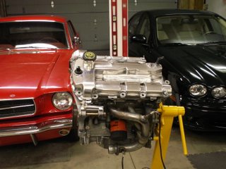
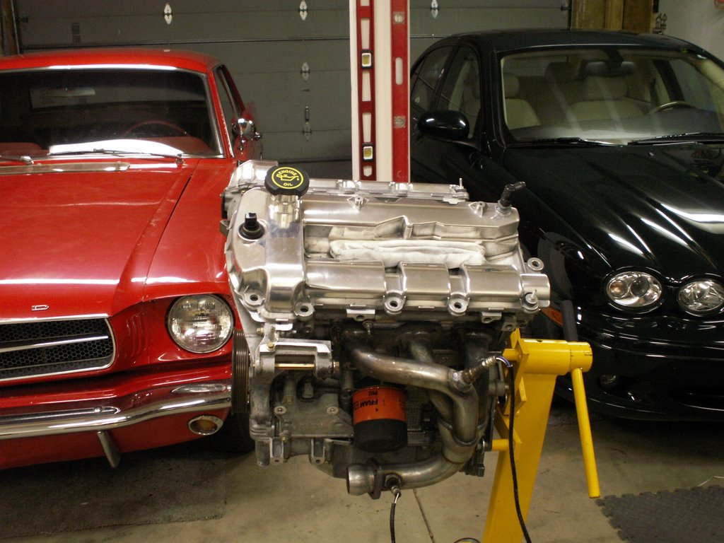
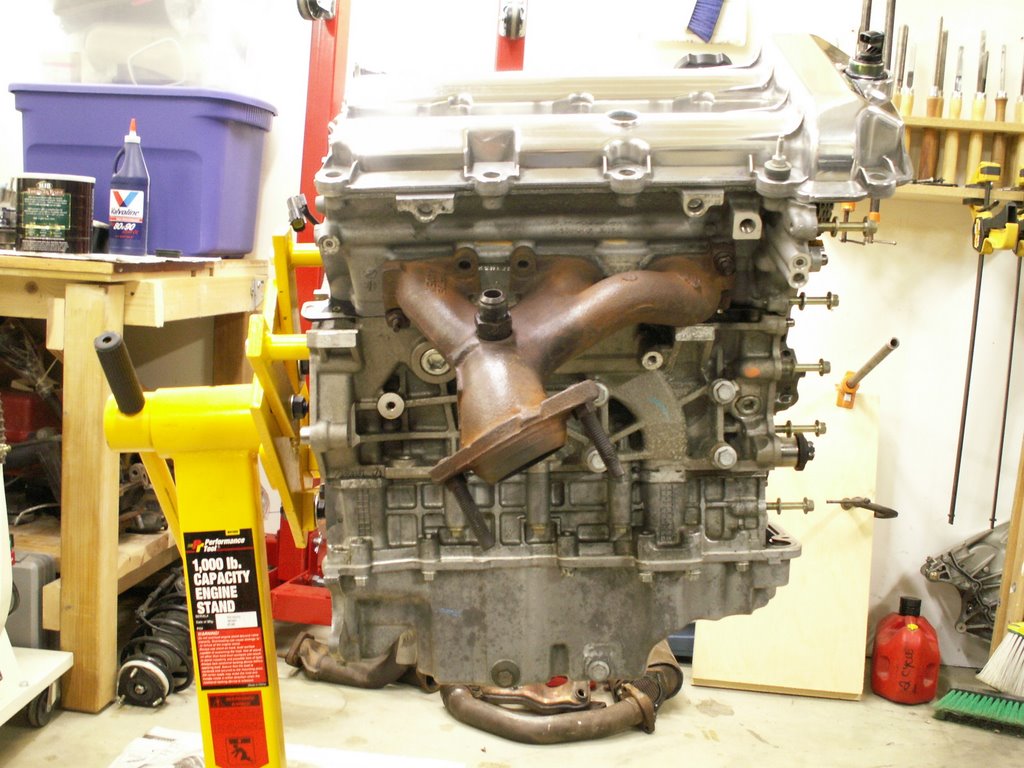
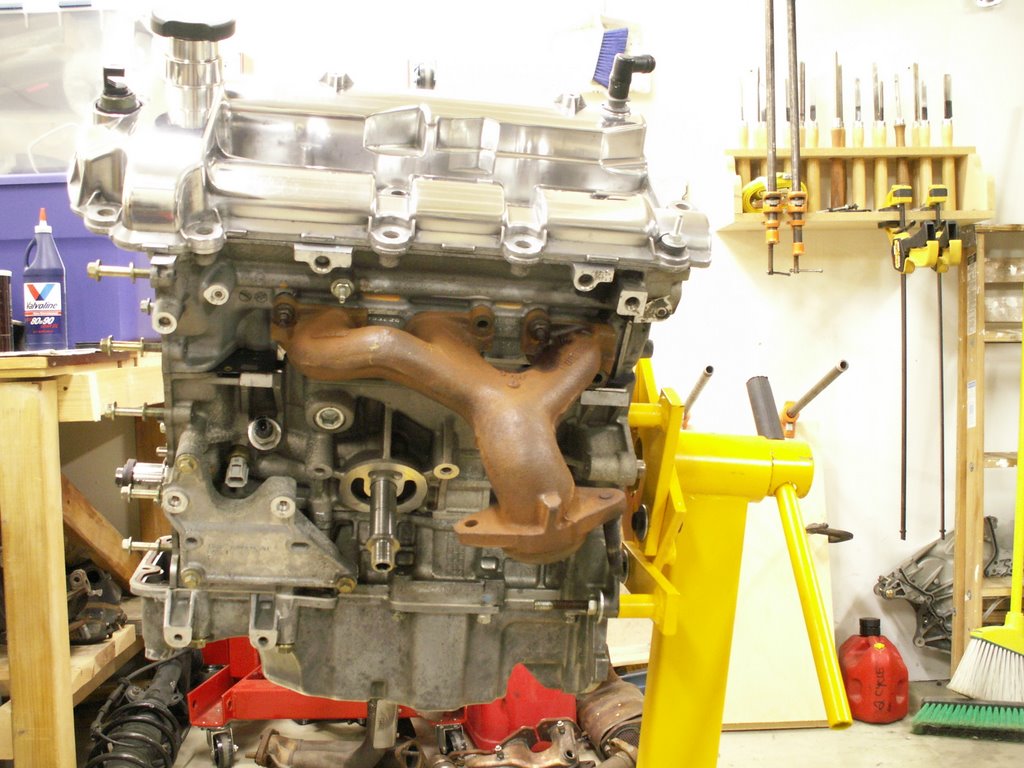
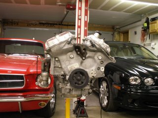 The front of the motor with timing cover back in place.
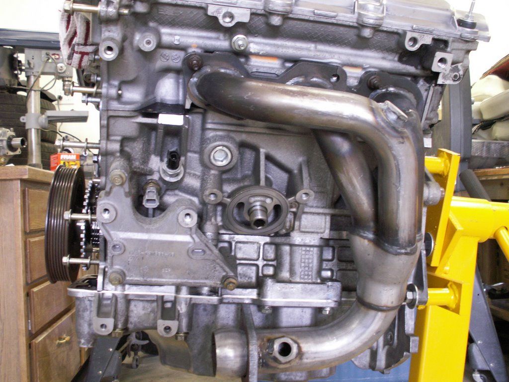
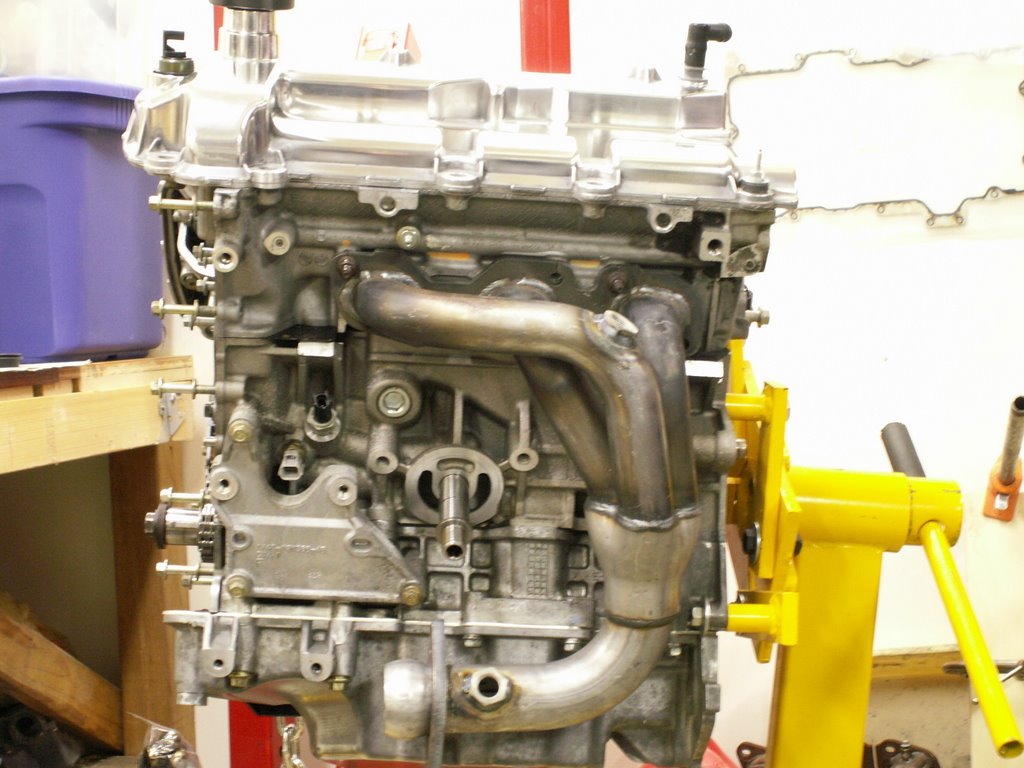
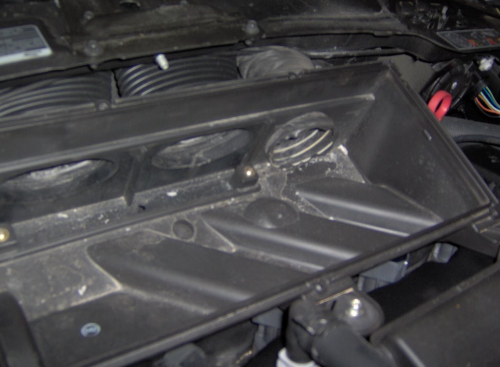
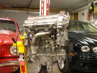 The back bank looking much cleaner with the factory exhaust plumbing missing.
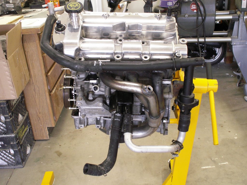
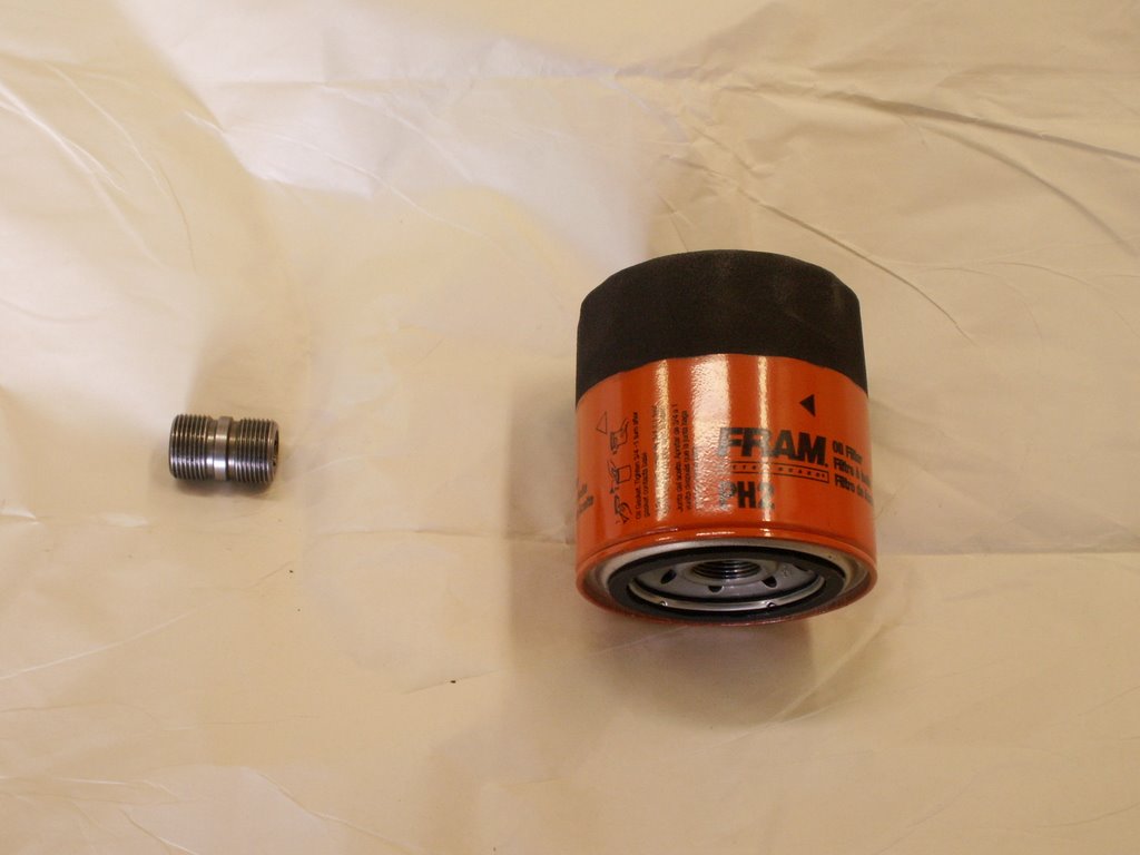
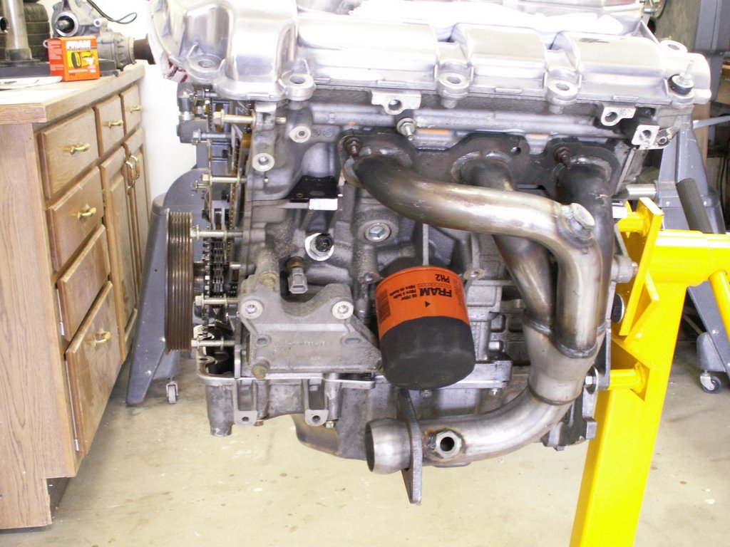
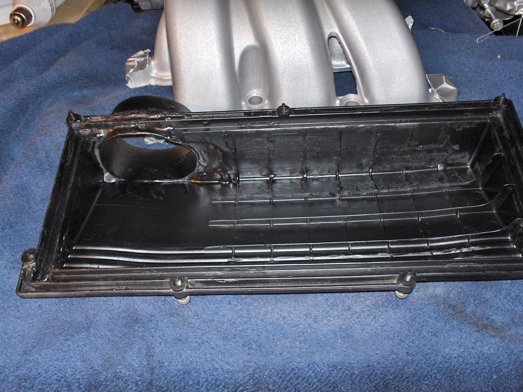
The front bank with new style oil filtering in place.
The back bank looking much cleaner with the factory exhaust plumbing missing.
The front bank with new style oil filtering in place.
 Thanks for everyone's patience on the exhaust system. Thinking about it, I received this engine Christmas of 2005. That is only six months ago. Hopefully, it will be running in my Sport by this Christmas.
Enjoy!
Thanks for everyone's patience on the exhaust system. Thinking about it, I received this engine Christmas of 2005. That is only six months ago. Hopefully, it will be running in my Sport by this Christmas.
Enjoy!
 The front of the motor with timing cover back in place.
 The back bank looking much cleaner with the factory exhaust plumbing missing.
The front bank with new style oil filtering in place.
The back bank looking much cleaner with the factory exhaust plumbing missing.
The front bank with new style oil filtering in place.
 Thanks for everyone's patience on the exhaust system. Thinking about it, I received this engine Christmas of 2005. That is only six months ago. Hopefully, it will be running in my Sport by this Christmas.
Enjoy!
Thanks for everyone's patience on the exhaust system. Thinking about it, I received this engine Christmas of 2005. That is only six months ago. Hopefully, it will be running in my Sport by this Christmas.
Enjoy!


 In this post I'll pursue those two valves and correct the clearances. I'll just cover what I need to get to those two shims. I'll put assembly in some future post; otherwise, this would take up a lot of space and pics.
The Jaguar Duratec head design is unique in its application for the X-Type. The 2.5L and 3.0L both use the same layout, except the valves are slightly larger in the 3.0L. This is a double overhead cam design with a mechanical valve train and not hydraulic as other Duratecs are. Jaguar designed a variable valve timing (VVT) feature and works by varying the cam positions of the intake cams only. Their positions change in relation to the position of the crankshaft and exhaust cams to optimize torque during the rpm range from idle to redline.
The system works using a hydraulic two-port pump design, fed with engine oil and pressure, and controlled by the ECM. The ECM sends a signal to the pumps to close one port, open the other to advance the intake cams to create the optimal combination of performance/fuel economy/emissions at certain places during the RPM/load range, then sends the opposite signal (close that port, open the first) to retard the intake cams.
These electric/hydraulic pumps (one for each intake cam) are VERY sensitive to oil viscosity, so it is important to use the "right" oil weight, otherwise, the VVT might not function even though the ECM sends signals to advance or retard. 5W 30 multi-grade is the best weight range for most driving conditions and tested to be the required weight by Jaguar. Note that the engine oil cap has 5W 30 printed on its top. If another weight oil is used in a Duratec the W should never be higher than 5W, so the only other option might be 0W 30.
Enough philosophy - let's get our hands dirty. If you remember from past posts, I have the Duratec torn down to expose the cams. It is down to the block and heads, but the timing cover was left in place. Here we'll remove the timing cover and timing chains so the intake cam can be removed, then we can finally reveal/remove the shim buckets. These shims on buckets control the valve clearance. They are a two piece design (bucket and shim). There is no way around using any special tool to depress the bucket and remove just the shim like so many other mechanical lifter DOHC designs, including other Jaguar engines. If someone has I'd like to hear from them.
So, first step is to remove the crankshaft pulley. There is a special Jaguar tool used to hold the pulley from turning anti-clockwise as the retaining bolt is broken loose. Remember, it is critical that the crankshaft only turn clockwise for two reasons - the timing chain tensioners can be damaged if they travel backwards and the journal bearings are specially ground to minimize wear in one direction. If the engine were to turn anti-clockwise, burrs might be created on the bearings - a true no, no.
I made my own special tool to hold the crank pulley using an old serpentine belt. Break the retaining bolt loose, then use a three legged gear puller to back the pulley off the crankshaft and key. After the pulley is removed, loosen and remove all of the bolts holding the timing cover in place. With all bolts out, the timing cover needs to be LIGHTLY tapped to break the gasket bonds. It's important to use something soft (such as a piece of wood) with a rubber mallet. Do not hit the cover with a hammer! Place the wood on a non-gasketed surface, then lightly tap the wood - Capish?
Here is a picture of the timing cover. It is a HUGE (and ugly), heavy aluminum casting. It will come with a crankshaft oil seal (that I will replace before reassembly), the cam position sensors, and the crankshaft position sensor. Integral to the casting are the entire mounting ears (brackets) for the alternator and the power steering pump. Be careful how you handle this piece with its bulk.
In this post I'll pursue those two valves and correct the clearances. I'll just cover what I need to get to those two shims. I'll put assembly in some future post; otherwise, this would take up a lot of space and pics.
The Jaguar Duratec head design is unique in its application for the X-Type. The 2.5L and 3.0L both use the same layout, except the valves are slightly larger in the 3.0L. This is a double overhead cam design with a mechanical valve train and not hydraulic as other Duratecs are. Jaguar designed a variable valve timing (VVT) feature and works by varying the cam positions of the intake cams only. Their positions change in relation to the position of the crankshaft and exhaust cams to optimize torque during the rpm range from idle to redline.
The system works using a hydraulic two-port pump design, fed with engine oil and pressure, and controlled by the ECM. The ECM sends a signal to the pumps to close one port, open the other to advance the intake cams to create the optimal combination of performance/fuel economy/emissions at certain places during the RPM/load range, then sends the opposite signal (close that port, open the first) to retard the intake cams.
These electric/hydraulic pumps (one for each intake cam) are VERY sensitive to oil viscosity, so it is important to use the "right" oil weight, otherwise, the VVT might not function even though the ECM sends signals to advance or retard. 5W 30 multi-grade is the best weight range for most driving conditions and tested to be the required weight by Jaguar. Note that the engine oil cap has 5W 30 printed on its top. If another weight oil is used in a Duratec the W should never be higher than 5W, so the only other option might be 0W 30.
Enough philosophy - let's get our hands dirty. If you remember from past posts, I have the Duratec torn down to expose the cams. It is down to the block and heads, but the timing cover was left in place. Here we'll remove the timing cover and timing chains so the intake cam can be removed, then we can finally reveal/remove the shim buckets. These shims on buckets control the valve clearance. They are a two piece design (bucket and shim). There is no way around using any special tool to depress the bucket and remove just the shim like so many other mechanical lifter DOHC designs, including other Jaguar engines. If someone has I'd like to hear from them.
So, first step is to remove the crankshaft pulley. There is a special Jaguar tool used to hold the pulley from turning anti-clockwise as the retaining bolt is broken loose. Remember, it is critical that the crankshaft only turn clockwise for two reasons - the timing chain tensioners can be damaged if they travel backwards and the journal bearings are specially ground to minimize wear in one direction. If the engine were to turn anti-clockwise, burrs might be created on the bearings - a true no, no.
I made my own special tool to hold the crank pulley using an old serpentine belt. Break the retaining bolt loose, then use a three legged gear puller to back the pulley off the crankshaft and key. After the pulley is removed, loosen and remove all of the bolts holding the timing cover in place. With all bolts out, the timing cover needs to be LIGHTLY tapped to break the gasket bonds. It's important to use something soft (such as a piece of wood) with a rubber mallet. Do not hit the cover with a hammer! Place the wood on a non-gasketed surface, then lightly tap the wood - Capish?
Here is a picture of the timing cover. It is a HUGE (and ugly), heavy aluminum casting. It will come with a crankshaft oil seal (that I will replace before reassembly), the cam position sensors, and the crankshaft position sensor. Integral to the casting are the entire mounting ears (brackets) for the alternator and the power steering pump. Be careful how you handle this piece with its bulk. 


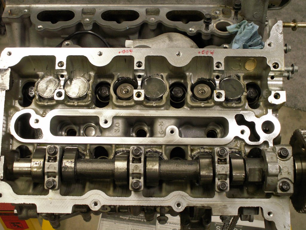
 Finally, here is a group picture that shows all of the parts removed to get to the buckets. From the left: the RH chain tensioner; the curved chain track; the two intake bucket shims; the fixed chain guide with the VVT pump; the intake cam from the RH bank. The chain was left on the crank sprocket as it can so easily be reversed.