Friday, April 03, 2009
Friday, April 27, 2007
Jaguar Journal Entry #2 - Trouble in the Trunk

Saturday, May 20, 2006
Motor Project # 16 - Timing Cover
 The front of the motor with timing cover back in place.
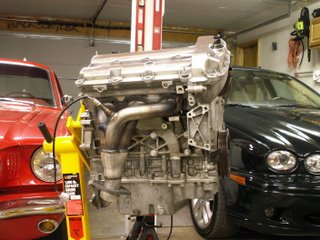 The back bank looking much cleaner with the factory exhaust plumbing missing.
The front bank with new style oil filtering in place.
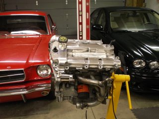 Thanks for everyone's patience on the exhaust system. Thinking about it, I received this engine Christmas of 2005. That is only six months ago. Hopefully, it will be running in my Sport by this Christmas.
Enjoy!
Sunday, May 07, 2006
Motor Project # 15 - Oil Filtering
 The first picture shows the mock up assembly. Right below the header you'll see the filter cooling radiator with inlet/outlet hoses. The larger hose on the left is inlet and is the bottom radiator hose. Coolant flows through coils that contact oil flowing into the filter. Coolant then flows out of the coolant radiator to the coolant system's thermostat. Connections here consist of two very small rubber hoses with a rigid aluminum pipe connector in the middle. These two small hoses will be prone to failure, and I will elimintate them in my modifications. BTW - The thermostat is located in the vertical pipe assembly to the right/rear of the headers. It is the triangular flange housing seen in this picture. The small hose immediately below it is the notorious TSB hose that had a tendancy to blow off and Jaguar issued the TSB to install a screw hose clamp. You'll see both the old and replacement clamps on the aluminum pipe left from when I removed this assembly. Jag techs would install the new clamp and not remove the old one.
A picture of just the filter and coolant housing as designed by Jaguar
 Here is a picture of the filtering components on the Jaguar design. The Cooling readiator is shown on the left. The extension stud in the middle and the factory numbered oil filter in a FRAM crossover, the XG3600.
  In my modified design, used with the header system, I will eliminate all of these parts including the extra coolant lines. With the header system and cat back design I am freeing up a lot of heat bulidup and congestion in the filtering area. By reducing the coolant line extensions I will improve the overall coolant flow in the system, eliminate these small hoses prone to failure on the road, and replace the factory oil filter with a larger capacity (FRAM PH 2) for increased oil filtering. The larger filter will also aid in natural cooling. For my design I will route the lower radiator hose directly to the coolant system's thermostat.
 Here is a picture of the replacement oil filtering components. The small stud shown here is from a circa 1999 V6 Duratec. It screws directly into the mounting location on the block of the existing filtering system. Then the oil filter mounts to that.
Here is a picture of the smaller stud installed in the engine block. In the engine manufacturing process, the oil filter flange is milled to specs the same way on all V6 D
 uratec variations, then different division users accessorize the filtering system according to their designs. This makes the PH 2 filter variation work directly on the original engine factory machined flange, which is a variation in itself. You can see the small stud installed on the circular flange directly under the first and second header pipe, counting from the left.
The final assembly with headers in place will look like this:
 I expect this modification, in addition to the headers and modifications to the coolant system will overall improve performance and clean up some "clutter" in the engine compartment.
Again, I appreciate your patience for those waiting to see the completion of the header system. It's been a busy time for my business and will continue in the near future.
Enjoy.
Monday, March 13, 2006
Motor Project # 14 - Waiting to Exhale, the 1st Sequel
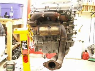

 OPTION I - Generic Duratec Exhaust Manifolds:
In the first option I am using a stock set of exhaust manifolds from a 1999 Taurus 3.0L. These are much more balanced left to right, have much better flow than the stock Jaguar versions and, when I get the crossovers and collectors completed, will have a cat back design located past the collector. It is intended to be a cost effective way of improving exhaust flow, and with less effort to accomplish the changeover.
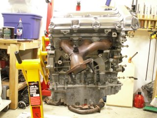
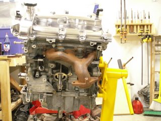 OPTION II - Exhaust Header, Crossover, Collector, Single Hi-Flow Cat Solution:
Here are the same pics showing the full header solution. I'll mock the crossover and collector from corrugated tubing, then have them built in solid tubing at a muffler shop. Here too, the cat will be pushed back past the collector and will find itself under the chassis floor pan.
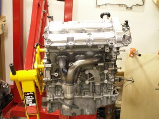
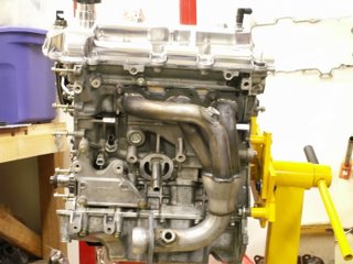
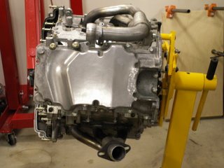
 Now I will complete the fab mock ups to create the crossovers and collectors for both exhaust options. I've taken these pictures carefully and will use them in the first found of measurements for the mock ups, comparing the placements to the first set of pics showing the stock system. Then in final steps, I will use my X-Type to finish the layouts and fittings. These will be covered in future projects with the same project name.
Hope you find this project informative - enjoy!
Saturday, March 04, 2006
Motor Project # 13 - Rewind (Retime)
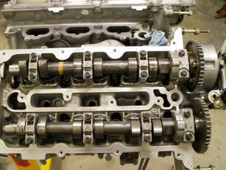
- Remember that each cap MUST go back in the same place and same orientation.
- The caps have locating dowels on each bolt hole so they're not going to seat completely flat from the start.
- Generously lubricate the entire cam and bearing journals with assembly grease, place the cam in position, lubricate the caps and the shims.
- Be very careful with the fourth (larger) cap. It has a diagonal oil passage that is drilled from the bearing surface to the lateral face bearing surface. Do NOT pack this with assembly grease as it will take too long on engine startup for the grease to dissolve. Make certain this passage is clear!
- This is a General note. I'll make it once as I will probably forget somewhere in the future. I use anti-seize lubricant on ANY steel bolt being threaded into aluminum! All of the cam cap bolts are steel and the head is aluminum.
- The key to correct cam assembly is: start all bolts and thread down evenly! Once the cap dowels begin to make contact in the head, I only turn each bolt 1/2 turn starting on the far right (fourth cap), inside/outside bolt, then move to the next cap, 1/2 turn inside/outside bolt, and so on. Return to the right side and repeat another 1/2 turn on all bolts until all caps are seated but hardly tightened.
- Now you are ready for the torque wrench. The torque sequence on these cam caps is the same we've been using to run the bolts down. Start at the large cap - inside/outside bolts, the move to the next cap, repeat, capish? JTIS torque spec is: 10 nm. Don't (ever) retorque. Click once, go on to the next bolt, capish?
Now let's time! To retime the right bank there is the easy way or the Jaguar JTIS way. I'm going to show you the easy way because if you try to read and follow JTIS, it'll make you crazy, your hair will fall out, your fingernails will grow to 12 inches long and we'll have to visit you in a special place and wipe the oatmeal off your chin...I'm sure you don't want that!
All of the JTIS assembly stuff (Engine - 303-01; steps 28 through 31) are pretty much malarchy! The clock settings are mostly meant to put the intake/exhaust cams (one bank at a time) in the most relaxed positions. The actual timing of the intake/exhaust cams to the crankshaft is never really spelled out and there is a significant chance the engine will not be timed correctly following these rote instructions. Never is the intuitive instruction given here.
Principles of Timing a Duratec: If you forget everything I've ever said, just DON'T forget this:
For the right bank: 23 chain links from the crank keyway to the exhaust cam timing mark, another 15 links to the intake timing mark.
For the left bank: 23 chain links from the crank keyway to the INTAKE cam timing mark, another 15 links to the exhaust timing mark(intake/exhaust cams reversed left/right banks). It's just that simple!
With this information you can practically put a blindfold on and time this engine with tactile skills, perfectly every time. Here are some subordinate rules:
- For timing, remember that the one and only common and FIXED position is the Keyway on the crankshaft. Everything gets positioned from this point.
- ALL link counting (either bank) and ANY rotation of anything is CLOCKWISE.
- Put anti-seize compound on any steel bolt threaded into aluminum.
- Put a liberal coating of assembly lube on all parts - chain, guides, etc.
First step, assemble the stationary chain guide. It is the one piece cast aluminum frame containing the intake VVT pump solenoid. It has three bolts, one of which gets tightened first. Also, don't forget the small dime sized o-ring between the pump and the oil passage that feeds the the VVT. Here is a picture. 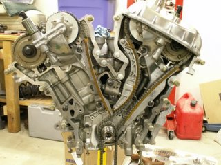 The bolt that gets tightened and torqued first is the one directly under the exhaust cam sprocket. However, you still want to hand tighten all three, the other two are top/bottom of the chain guide. The reason you're torquing the bolt under the cam sprocket first is because it seats the o-ring with the VVT oil passage. JTIS torque spec is: 25 nm.
Now you're ready to place the chain on the sprockets. The relative ideal position for the right bank timing is: crankshaft keyway 7 o'clock (make that pm not am...nah, only kidding about the pm), exhaust mark at 8 o'clock pm...nah still kidding, and intake mark at 1 o'clock. This is just where we positioned everything to disassemble.
Place the chain (so it will rotate in the same direction it was removed) over the intake/exhaust sprockets. Start with the mark on the exhaust cam and count 15 links to the intake cam. This now puts the two cams in time with each other. 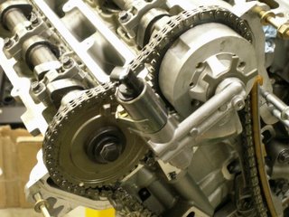
If you look closely at this picture, click to enlarge, you'll see the white dot mark on the exhaust cam sprocket, and the white dot mark on the intake cam sprocket is smaller, almost straight up at 12 o'clock. You can count the 15 links in the picture.
Now continue to thread the chain CLOCKWISE over the stationary chain guide and engage with the crankshaft sprocket for the right bank. Remember, you need 23 links from the keyway to the exhaust timing dot. The chain will seem very large and you'll have plenty of room to move it because the adjustable chain guide is not installed at this point. 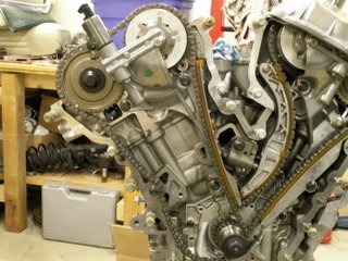
See this picture to view the chain and timing to this point. Before the adjustable guide is assembled, the link count and the slack must be taken up all in one direction - what direction? This is a test. CLOCKWISE from the exhaust timing dot all the way around to the crank keyway. If there is too much slack on the stationary guide then turn the crank slightly CLOCKWISE (See how easy this is). If there is not enough slack to make the 23 tooth count, then rock the intake/exhaust cams together back forth until you can make this count.
Now this will sit for a moment so we can prepare the tensioner. The tensioner is a LOAD/LOCK design. It has a sprung piston that puts tension on the adjustable guide and a secondary ratchet locked stop to keep the chain from gaining slack under load. To load the tensioner, fully collapse the piston in a bench vise, then the fixed ratchet stop must be released and placed down at the shoulder of the piston. With this, a slot in the ratchet stop will appear through an inspection hole in the body of the tensioner. Place a paper clip, or drill rod in the inspection hole and this will hold the piston and ratchet in the fully collapsed position. Here is a picture of the tensioner loaded and locked. I used a small drill bit as my paper clip. 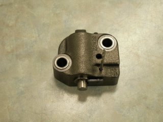
Now the tensioner along with the adjustable chain guide can be assembled. The guide just rides on a dowel pin and, without the tensioner in place, has plenty of freeplay for assembly. At this point you can push on the guide until it bears pressure on the chain and you'll see the right bank timing really coming to life now. As you hold it against the chain, now is a good time to recheck the link timing. Start at the crank keyway and count (how many links)? to the exhaust sprocket dot. Continue counting (in what direction)? and (how many links)? to the intake white dot. If everything is what you now know it should be, then you're ready to install the tensioner. Use the two bolts coated with anti-seize, thread them in by hand. There should be some play for the guide as the piston is still fully collapsed. Tighten the two bolts to (JTIS) 25 nm. Before you release the drill bit (to release the piston), there is a recess in the guide where the piston rides. There is enough play in the guide that it is possible for the piston to sit outside this recess. Once that is in place, release the drill bit. The piston will exert the correct amount of pressure to the guide at this time. Finally move the secondary ratchet stop in place under the guide recess and Voila!...Timed! 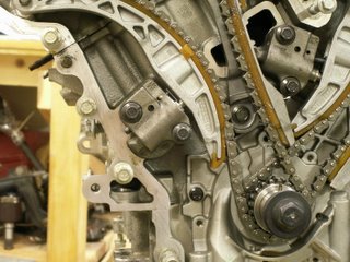
Here is a picture of the tensioner in place, torqued, just before the drill bit is released.
One final step: Rotate the crankshaft two complete turns (what direction)? to approximately the same place 7 o'clock pm (get you with that every time don't I), and recount 23, 15, to make sure you're timed correctly.
Well, that's quite the round about way (and the JTIS way) to do a valve adjustment on the V6. All together several hours of labor (Jaguar book says 5/6 hours' labor) and, again, about $400 retail in parts which includes just two shims.
How about a shortcut. One that only involves removing the valve covers then removing replacing the shims directly under the cams without removing them. Most manufacturers make a tool for this. It holds the bucket down so the shim can be removed when the cam lobe is opposite the shim. Talking to a few technicians, there is a tool like this for the V8, some talk about a tool, maybe, for the S-Type...Long story short, no one really knows and JTIS doesn't for sure.
With the cam lobe opposite the shim, reach back behind the cam with a flat blade screw driver, taped with black electrical tape. You need to catch the very edge of the bucket (it's a delicate operation). Force the bucket down in its recess, use a strong industrial magnet to catch the shim, it can be dislodged and removed. With the shim out you can release the screwdriver and no contact with the cam is made. Select the correct shim. Once again, place the screw driver on the edge of the bucket, depress (doesn't take a lot of pressure), slip the new shim in. Make sure it's seated in the bucket, release the screw driver...Voila!
Here is a picture with the screw driver in place and the new shim ready to go in. 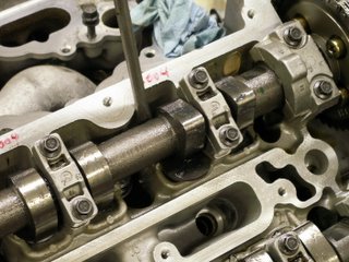
Why should you care about this project? I'm not expecting most to do their own valve adjustments, and I start with the belief that all shops are honest, but in case one is not, there is a WHOLE BUNCH of money to be made on a valve adjustment. If the shop wants to quote JTIS procedure on an X-Type, they will probably include 6 to 8 hours of labor, or more, and anywhere from $400 to $600 in parts. Then they can perform this shortcut and cut the labor down to one and a half or two hours. That's why you want to know this, even if you never DIY!
At this time I am proceeding to seal the engine back up. Next, I'll reinstall the lower end stuff removed in earlier posts. pan baffles, oil sump pick up, oil pan. I'm fairly convinced there isn't much I can do with the innards of the Duratec, even crossing over to the generic side. At least for the moment.
On the other hand, there is plenty to do outside, with intake and exhaust. I have been very busy pursuing two options for more efficient exhaust. One is a moderate design using other Duratec parts and a cat back layout. The other involves a full blown header set with cat back also. I will be previewing both options in mock up very soon. There is still a lot of work to do with building crossover pipes, etc., but I'm feeling very optimistic about the exhaust. Both options, BTW, still fully utilize the factory ECM outputs and factory mapping. Then Karl Wolf has a muffler mod that I'll include in the final exhaust mod.
Hope you enjoy.
Saturday, February 18, 2006
Motor Project # 12 - Deep Breathing Exercise!


 A picture of the lower portion of the airbox is shown here in place with the new air inlet modification. See the third air inlet to the far right of the box, next to the two original oval inlets.
  Here is a picture of the air box reassembled after all of the modifications. Very little has changed in appearance from the stock air box. I use a K&N filter, but you can use a stock filter. Just make sure to replace it regularly.
Cost? About $15.00 in parts. Time? One hour for the simple solution. Two to three hours for the more complex solution. The great thing about these mods is that unless you know what you are looking at, the air intake looks totally stock and really does not change anything but allows more airflow. You may notice a very small increase in intake growl but it is only due to the increase in airflow, not the growl associated with an aftermarket air intake. These aftermarket intakes take air from under the hood. Some of the benefits of these kits are negated by the additional heated underhood air.


